Preface
Legal Notices
Copyright © 2024, 2025, 2026 SEQUANS Communications
All information contained herein and disclosed by this document is the proprietary property of SEQUANS Communications, and all rights therein are expressly reserved. Acceptance of this material signifies agreement by the recipient that the information contained in this document will be used solely for the purposes set forth herein. Acceptance of this material signifies agreement by the recipient that it will not be used, reproduced in whole or in part, disclosed, distributed, or conveyed to others in any manner or by any means – graphic, electronic, or mechanical, including photocopying, recording, taping, or information storage and retrieval systems – without the express written permission of SEQUANS Communications.
All Sequans’ logos and trademarks are the property of SEQUANS Communications. Unauthorized usage is strictly prohibited without the express written permission of SEQUANS Communications. All other company and product names may be trademarks or registered trademarks of their respective owners. Products and services of SEQUANS Communications, and those of its licensees may be protected by one or more pending or issued U.S. or foreign patents.
Because of continuing developments and improvements in design, manufacturing, and deployment, material in this document is subject to change without notification and does not represent any commitment or obligation on the part of SEQUANS Communications. SEQUANS Communications shall have no liability for any error or damages resulting from the use of this document.
Document Revision History
| Revision | Date | Applicable from Software Revision | Changes |
|---|---|---|---|
| 5 | Aug. 2026 | 8.2.3.1-65130 |
|
| 4a | Jan. 2026 | LR8.2.2.1-63493 |
|
| 4 | Oct. 2025 | LR8.2.2.1-63493 |
|
| 3c | Jan. 2025 | LR8.2.1.0-61488 |
|
| 3b | Oct. 2024 | LR8.2.1.0-61488 |
|
| 3a | Sept. 2024 | LR8.2.1.0-61488 |
|
| 3 | May 2024 | LR8.2.0.5-60964 |
|
| 2 | July 2023 | LR 8.2.0.2-59200 |
|
| 1 | April 2023 | LR 8.2.0.0 | N/A |
AT Channel Control Commands
Backwards Compatibility NOP Commands: AT&K, ATL, ATM, ATN, ATS0, ATX
Syntax
| Command | Possible Response(s) |
|---|---|
|
AT&K |
OK |
Description
These commands are included for backwards compatibility with existing software. They are ignored by
the modem and return OK.
Command Line Editing Character: ATS5
| Mode | LTE-M – NBIoT |
| Type | Synchronous |
| Prerequisite | – |
| Time-out | 1 s |
| Persistency | Not reboot persistent (see Write Active Profile in Memory: AT&W) |
Syntax
| Command | Possible Response(s) |
|---|---|
| ATS5=[<value>] | OK |
| ATS5? | <value> |
Description
This ‘S-parameter’ represents the decimal IA5 value of the character interpreted by the DCE as a request to delete from the command line the immediately preceding character.
Defined Values
- value
- Integer: 0..127. Set the command line editing character to this value. The recommended default value is 8, i.e. the ‘Backspace’ character (BS, IA5 0/8).
Command Line Termination Character: ATS3
| Mode | LTE-M – NBIoT |
| Type | Synchronous |
| Prerequisite | – |
| Time-out | 300 ms |
| Persistency | Not reboot persistent (see Write Active Profile in Memory: AT&W) |
Syntax
| Command | Possible Response(s) |
|---|---|
| ATS3=[<value>] | OK |
| ATS3? | <value> |
Description
This ‘S-parameter’ represents the decimal IA5 value of the character recognized by the DCE as
terminating a DTE command line. It is also generated by the DCE as part of the header, trailer, and
terminator for result codes and information text, along with the S4 parameter (see
the description of the V parameter for usage).
The previous value of S3 is used as the command line termination character of a new
ATS3 setting command. However, the result code issued uses the new value of
S3. For example, if S3 is set to 13 and the command
‘ATS3=30’ is issued, that command must end with a CR character (IA5 0/13), but
the result code issued will use the character with the ordinal value 30 (IA5 2/14) in place of the
CR.
Defined Values
- value
- Integer: 0..127. Set command line termination character to this value. The mandatory default value is 13, or ‘Carriage Return’ (CR, IA5 0/13).
DCE Response Format: ATV
| Mode | LTE-M – NBIoT |
| Type | Synchronous |
| Prerequisite | – |
| Time-out | 300 ms |
| Persistency | Not reboot persistent (see AT&W) |
Syntax
| Command | Possible Response(s) |
|---|---|
| ATV[<value>] |
|
Description
Setting this parameter determines the contents of the header and trailer transmitted with result codes and information responses. It also determines whether result codes are transmitted in numeric or alphabetic (so-called ‘verbose’) form. The text portion of information responses is not affected by this setting.
| V0 | V1 | |
|---|---|---|
| Information Response | <text><S3><S4> |
<S3><S4><text><S3><S4> |
| Result Codes | <numeric code><S3> |
<S3><S4><verbose code><S3><S4> |
Defined Values
- value
- Integer: 0 or 1.
Echo: ATE
| Mode | LTE-M – NBIoT |
| Type | Synchronous |
| Prerequisite | – |
| Time-out | 300 ms |
| Persistency | Not reboot persistent (see AT&W) |
Syntax
| Command | Possible Response(s) |
|---|---|
| ATE<value> | OK |
Description
The setting of this parameter determines whether or not the DCE echoes (sends back) characters received from the DTE during command state and online command state.
Defined Values
- value
- Integer: 0 or 1.
Enable Smart Terminal: AT+SMART
| Mode | CatM – NBIoT |
| Type | Synchronous |
| Requirements | – |
| Time-out | 300 ms |
| Settings | Not reboot persistent |
Syntax
| Command | Possible response(s) |
|---|---|
| AT+SMART=[<enable>] | OK |
| AT+SMART=? | OK |
Description
This command switches the AT command interface between the default ‘dumb’ text-based terminal mode and a human-friendly smart terminal mode (with, for example, up and down arrow search in command history and in-line command editing).
Defined Values
- enable
- Integer: 0 or 1. Enable (1) or disable (0) the smart terminal. The default value is 1.
Repeat Command Line: A/
| Mode | LTE-M – NBIoT |
| Type | Synchronous |
| Prerequisite | – |
| Time-out | 300 ms |
| Persistency | N/A |
Syntax
| Command | Possible Response(s) |
|---|---|
| A/ |
Description
If the prefix A/ or a/ is received, the DCE immediately repeats the preceding
command. No editing is possible, and no termination character is necessary. A command may be
repeated multiple times, if desired. Responses to the repeated command line shall be issued using
the parity and format of the original command line, and the rate of the A/. If
A/ is received before any command line has been executed, the preceding command line
is assumed to have been empty, which results in an OK result code).
Reset to Default Configuration: ATZ
| Mode | LTE-M – NBIoT |
| Type | Synchronous |
| Prerequisite | Not Available in Manufacturing Mode |
| Time-out | 300 ms |
| Persistency | N/A |
Syntax
| Command | Possible Response(s) |
|---|---|
| ATZ[0] | OK
|
Description
This command instructs the DCE to reset all parameters to their factory defaults as specified by the manufacturer. This may include the hardware settings such as configuration switches or reset persistent parameters (if implemented). If the DCE is connected to the network, it is disconnected, thereby terminating any call in progress.
ATZ command because they may be ignored. Response Formatting Character: ATS4
| Mode | LTE-M – NBIoT |
| Type | Synchronous |
| Prerequisite | – |
| Time-out | 300 ms |
| Persistency | Not reboot persistent (see AT&W) |
Syntax
| Command | Possible Response(s) |
|---|---|
| ATS4=[<value>] | OK |
| ATS4? | <value> |
Description
This ‘S-parameter’ represents the decimal IA5 value of the character generated by the DCE as part of
the header, trailer, and terminator of result codes and information text, along with the
S3 parameter (see the description of the V parameter for usage).
If the value of S4 is changed in a command line, the result code issued in response
to that command line will use the new value of S4.
Defined Values
- value
- Integer: 0..127. Set response formatting character to this value. The recommended default value is 10, i.e. the Line Feed character (LF, IA5 0/10).
Result Code Suppression: ATQ
| Mode | LTE-M – NBIoT |
| Type | Synchronous |
| Prerequisite | – |
| Time-out | 300 ms |
| Persistency | Not reboot persistent (see AT&W) |
Syntax
| Command | Possible Response(s) |
|---|---|
| ATQ[<value>] |
|
Description
The setting of this parameter determines whether the DCE transmits result codes to the DTE or not. When result codes are being suppressed, no portion of any intermediate, final, or unsolicited result code – header, result text, line terminator, or trailer – is transmitted. Information text transmitted in response to commands is not affected by this parameter.
Defined Values
- value
- Integer: 0 or 1.
Select TE Character Set: AT+CSCS
| Mode | LTE-M – NBIoT |
| Type | Synchronous |
| Prerequisite | – |
| Time-out | 300 ms |
| Persistency | Not Reboot Persistent |
Syntax
| Command | Possible Response(s) |
|---|---|
| AT+CSCS=<charset> | OK |
| AT+CSCS? |
|
| AT+CSCS=? |
|
Description
The “Set” command informs the TA which character set <charset> is used by the TE. The TA can then convert strings between TE and MT character sets.
Defined Values
- charset
- String.
Control Plane Data Commands
CIoT Optimisation Configuration: AT+CCIOTOPT
| Mode | NBIoT |
| Type | Synchronous |
| Prerequisite | – |
| Time-out | – |
| Persistency | N/A |
Syntax
| Command | Possible Response(s) |
|---|---|
| AT+CCIOTOPT=[<n>[,<supported_UE_opt>[,<preferred_UE_opt>]]] | OK or +CME ERROR: <err> |
| AT+CCIOTOPT? |
|
| AT+CCIOTOPT=? |
|
| URC | +CCIOTOPTI: <supported_Network_opt> |
Description
This command controls which CIoT EPS optimisations the UE indicates as supported and preferred in the ATTACH REQUEST and TRACKING AREA UPDATE REQUEST messages. The command also allows reporting of the CIoT EPS optimisations that are supported by the network. A UE supporting CIoT functionality may support control plane CIoT EPS optimisation or user plane CIoT EPS optimisation or both (see 3GPP TS 24.301 [83], sub-clause 9.9.3.34). Based on the application characteristics the UE may prefer to be registered for control plane CIoT EPS optimisation or for user plane CIoT EPS optimisation (see 3GPP TS 24.301 [83], subclause 9.9.3.0B). Further the network may support control plane CIoT EPS optimisation or user plane CIoT EPS optimisation or both (see 3GPP TS 24.301 [83], sub-clause 9.9.3.12A).
The set command is used also to control the unsolicited result code +CCIOTOPTI. An
unsolicited result code +CCIOTOPTI: <supported_Network_opt> is used to indicate the
supported CIoT EPS optimizations by the network.
The read command returns the current settings for supported and preferred CIoT EPS optimisations and the
current status of unsolicited result code +CCIOTOPTI.
The test command returns values supported as compound values.
See also Mobile Termination Error Result Code: +CME ERROR for <err> values.
Defined Values
- n
- Integer. Enables or disables reporting of unsolicited result code
+CCIOTOPTI. - supported_UE_opt
- Integer: 0, 1, 2 or 3. Indicates the UE's support for CIoT EPS optimisations.
- preferred_UE_opt
- Integer: 0, 1 or 2. Indicates the UE's preference for CIoT EPS optimisations.Note:1 is the only supported choice in the current software release.
- supported_Network_opt
- Integer: 0, 1, 2 or 3. Indicates the Network support for CIoT EPS optimisations.Note:1 is the only supported choice in the current software release.
Reporting Terminating Data using the Control Plane: AT+CRTDCP
| Mode | NBIoT |
| Type | Synchronous |
| Prerequisite | – |
| Time-out | – |
| Persistency | N/A |
Syntax
| Command | Possible Response(s) |
|---|---|
| AT+CRTDCP=[<reporting>] | OK or +CME ERROR: <err> |
| AT+CRTDCP? |
|
| AT+CRTDCP=? |
|
Description
This command enables or disables reporting of data from the network to the MT transmitted using the
control plane in the downlink direction. If reporting is enabled, the MT returns the unsolicited result
code +CRTDCP: <cid>,<cpdata_length>,<cpdata> when data is received from
the network.
The read command returns the current settings.
The test command returns supported values as compound values.
See also Mobile Termination Error Result Code: +CME ERROR for <err> values.
Defined Values
- reporting
- Integer: 0 or 1. Enable or disable reporting.
- cid
- Integer. A numeric parameter which specifies a particular PDP context or EPS bearer context definition. The <cid> parameter is local to the TE-MT interface and identifies the PDP or EPS bearer contexts which have been setup via AT command (see the AT+CGDCONT and AT+CGDSCONT commands).
- cpdata_length
- Integer. Size of the <cpdata> information element in bytes. 0 when there are no data to transmit.
- cpdata
- Byte string. User data container contents (refer to 3GPP TS 24.301 [83] sub-clause 9.9.4.24). When there is no data to transmit, the <cpdata> must be empty (""). This parameter must not be converted as defined by the AT+CSCS command. The coding format of the user data container and the maximum length of <cpdata> are implementation specific.
Sending Originating Data using the Control Plane: AT+CSODCP
| Mode | NBIoT |
| Type | Synchronous |
| Prerequisite | – |
| Time-out | – |
| Persistency | N/A |
Syntax
| Command | Possible Response(s) |
|---|---|
| AT+CSODCP=<cid>,<cpdata_length>,<cpdata> [,<RAI>[,<type_of_user_data>]] | OK or +CME ERROR: <err> |
| AT+CSODCP=? |
|
Description
This command transmits data over the control plane to the network via MT. The context identifier <cid> is used to link the data to a particular context.
- Is expected to be completed with this uplink data transfer; or
- Is expected be completed with the next received downlink data.
This command causes transmission of an ESM DATA TRANSPORT message, as defined in 3GPP TS 24.301 [83].
Test command returns range of supported <cid>s, the maximum number of bytes of user data indicated by <cpdata_length>, supported <RAI>s and supported <type_of_user_data>s as compound values.
See also Mobile Termination Error Result Code: +CME ERROR for <err> values.
Defined Values
- cid
- Integer. A numeric parameter which specifies a particular PDP context or EPS bearer context definition. The <cid> parameter is local to the TE-MT interface and identifies the PDP or EPS bearer contexts which have been setup via AT command (see the AT+CGDCONT and Define Secondary PDP Context: AT+CGDSCONT commands).
- cpdata_length
- Integer. <cpdata> length in bytes. 0 if there are no data to transmit.
- cpdata
- Byte string. User data container contents (refer to 3GPP TS 24.301 [83] sub-clause 9.9.4.24). When there is no data to transmit, the <cpdata> must be empty (""). This parameter must not be converted as defined by the Select TE Character Set: AT+CSCS command. The coding format of the user data container and the maximum length of <cpdata> are implementation specific.
- RAI
- Integer: 0, 1 or 2. Value of the Release Assistance Indication, Release 13. Refer to 3GPP TS 24.301 [83] sub-clause 9.9.4.25.
- type_of_user_data
- Integer: 0 or 1. Regular or exception data.
Data Communication Equipement Identification Commands
Request Identification Information: ATI
| Mode | LTE-M – NBIoT |
| Type | Synchronous |
| Prerequisite | – |
| Time-out | 300 ms |
| Persistency | N/A |
Syntax
| Command | Possible Response(s) |
|---|---|
| ATI[<value>] | |
| ATI or ATI0 |
<manufacturer> |
| ATI1 |
<ue_version> |
| ATI2 |
|
| ATI3 |
<hwversion> |
Description
<value> may optionally be used to select from among
multiple types of identifying information, specified by the manufacturer. ATI0 command to indicate
which other features and commands are implemented in a DCE dooms software to
certain failure, since manufacturer implementations differ widely, even
amongst devices that may, coincidentally, respond with identical values.
Software developers should use ATI commands with extreme
caution. The amount of data returned by a specific implementation may vary
from a few bytes to several thousand bytes or more. Software must prepare to
receive ERROR responses if the value passed is not
recognised. ATI or ATI0 write commands reports device MT
manufacturer, MT model and the UE software version.
ATI1 write commands reports the UE and LR software versions.
ATI2 reports the device’s serial number and IMEISV.
ATI3 reports the device’s hardware version
and laser marking.
Defined values
- serial
- String (max. 64 characters). Device serial number.
- imeisv
- String. IMEISV (International Mobile station Equipment Identity and Software Version number). Refer to 3GPP TS 23.003 [7], sub-clause 6.2.2. The 16 digits of IMEISV are composed of Type Allocation Code (TAC) (8 digits), Serial Number (SNR) (6 digits) and the software version (SVN) (2 digits). The character set used is specified using the command Select TE Character Set: AT+CSCS.
- ue_version
- String. The module’s software version.
- lr_version
- String. Identical to <ue_version> with the build number added.
- hwversion
- String. The module’s hardware version.
- lasermarking
- String. The laser marking as engraved on the module’s top casing.
Example
ATI
SEQUANS Communications
GM02S
UE8.2.2.1
OK
ATI1
UE8.2.2.1
LR8.2.2.1-63473
ATI2
SERIAL: G2Q2106160008013
IMEISV: 0157700008800111
OK
Request International Mobile Subscriber Identity: AT+CIMI
| Mode | LTE-M – NBIoT |
| Type | Synchronous |
| Prerequisite | AT+CFUN=1 or 4. SIM card present |
| Time-out | 300 ms |
| Persistency | N/A |
Syntax
| Command | Possible Response(s) |
|---|---|
| AT+CIMI | <IMSI> |
| AT+CIMI=? | OK |
Description
Execution command causes the TA to return <IMSI>, which is intended to permit the TE to identify the individual SIM card or active application in the UICC (GSM or USIM) which is attached to MT.
See also Mobile Termination Error Result Code: +CME ERROR for <err> values.
Defined Values
- IMSI
- String (without double quotes). International Mobile Subscriber Identity.
Request Manufacturer Identification: AT+CGMI
| Mode | LTE-M – NBIoT |
| Type | Synchronous |
| Prerequisite | – |
| Time-out | 300 ms |
| Persistency | N/A |
Syntax
| Command | Possible Response(s) |
|---|---|
| AT+CGMI | <manufacturer> |
| AT+CGMI=? | OK |
Description
The execution of this command causes the TA to return one or more lines of information
<manufacturer>, chosen by the MT manufacturer, which is intended to permit
the user of the TA to identify the manufacturer of the MT it is connected to. Typically, a single
line containing the manufacturer’s name is returned, but manufacturers may elect to provide more
information, if desired.
Refer to Mobile Termination Error Result Code: +CME ERROR for <err> values.
Defined Values
- manufacturer
- String. The total number of characters, including line terminators, in the information text shall not exceed 2,048 characters. Text must not contain either ‘0<S3>’ or ‘OK<S3>’. Here, <S3> represents the value of the command line termination character. See Command Line Termination Character: ATS3
Request Model Identification: AT+CGMM
| Mode | LTE-M – NBIoT |
| Type | Synchronous |
| Prerequisite | – |
| Time-out | 300 ms |
| Persistency | N/A |
Syntax
| Command | Possible Response(s) |
|---|---|
| AT+CGMM | <model> |
| AT+CGMM=? | OK |
Description
This command causes the TA to send one or more lines of information text <model>, determined by the MT manufacturer, so that the user of the TA can identify the specific model of the MT it is connected to. Typically, the text will consist of a single line containing the name of the product, but manufacturers may elect to provide more information, if desired.
See also Mobile Termination Error Result Code: +CME ERROR for <err> values.
Defined Values
- model
- String. The total number of characters, including line terminators, in the information
text must not exceed 2048 characters. Text must not contain the sequence
0<S3>orOK<S3>. Here<S3>represents the value of the command line termination character. See ATS3.
Request Product Serial Number Identification: AT+CGSN
| Mode | LTE-M – NBIoT |
| Type | Synchronous |
| Prerequisite | – |
| Time-out | 300 ms |
| Persistency | N/A |
Syntax
| Command | Possible Response(s) |
|---|---|
| AT+CGSN[=<snt>] |
When <snt>=0 (or omitted) and the command succeeds: <sn> |
| AT+CGSN=? |
When TE supports <snt> and command successful: |
Description
Execution command causes the TA to return the IMEI (International Mobile station Equipment Identity number) and related information to identify the MT that the TE is connected to.
See also Mobile Termination Error Result Code: +CME ERROR for <err> values.
The command returns the supported values as a compound value. For a TA which does not
support <snt>, only OK is returned.
Defined Values
- snt
- Integer: 0, 1, 2 or 3. Serial number type requested.
- sn
- String. One or more lines of information text determined by the MT
manufacturer. Typically, the text will consist of a single line containing the
IMEI number of the MT, but manufacturers may elect to provide more information
if desired. The total number of characters, including line terminators, in the
information text must not exceed 2048 characters. Text must not contain the
sequence
0<CR>orOK<CR> - imei
- String in decimal format. IMEI: refer to 3GPP TS 23.003 [7], sub-clause 6.2.1. IMEI is composed of: the Type Allocation Code (TAC) (8 digits), the Serial Number (SNR) (6 digits) and the Check Digit (CD) (1 digit). Character set used in <imei> is specified using the command Select TE Character Set: AT+CSCS.
- imeisv
- String in decimal format. IMEISV: refer to 3GPP TS 23.003 [7], sub-clause 6.2.2. The 16 digits of IMEISV are composed of: the Type Allocation Code (TAC) (8 digits), the Serial Number (SNR) (6 digits) as per ETSI 3GPP TS 27.007 version 12.10.0 Release 12 23 ETSI TS 12 007 V12.10.0 (2015-10) and the software version (SVN) (2 digits). Character set used in <imeisv> is specified using the command Select TE Character Set: AT+CSCS.
- svn
- String in decimal format. Current SVN which is a part of IMEISV; refer 3GPP TS 23.003 [7], sub-clause 6.2.2. This allows identifying different software versions of a given mobile. Character set used in <svn> is specified using the command Select TE Character Set: AT+CSCS.
Examples:
-
To get <sn> which returns IMEI of the MT
AT+CGSN 490154203237518 OK -
To get <imei> which returns IMEI of the MT
AT+CGSN=1
+CGSN: "490154203237518"
OK
Request Product Serial Number Identification: AT+GSN
| Mode | LTE-M – NBIoT |
| Type | Synchronous |
| Prerequisite | – |
| Time-out | 300 ms |
| Persistency | N/A |
Syntax
| Command | Possible Response(s) |
|---|---|
| AT+GSN | (Information text) |
Description
This command is implemented as the Request Product Serial Number Identification: AT+CGSN command. They both behave in the same way. Please refer to AT+CGSN documentation for further details.
Request Revision Identification: AT+CGMR
| Mode | LTE-M – NBIoT |
| Type | Synchronous |
| Prerequisite | – |
| Time-out | 300 ms |
| Persistency | N/A |
Syntax
| Command | Possible Response(s) |
|---|---|
| AT+CGMR | <revision> |
| AT+CGMR=? | OK |
Description
Execution command causes the TA to return one or more lines of information text
<revision>, chosen by the MT manufacturer, so that the user of the TA can
identify the version, revision level or date, or other relevant information about the MT it is
connected to. Typically, the text will consist of a single line containing the version of the
product, but manufacturers may elect to provide more information if desired.
See also Mobile Termination Error Result Code: +CME ERROR for <err> values.
Defined Values
- revision
- String. The total number of characters, including line terminators, in the information
text must not exceed 2048 characters. Text must not contain the sequence
0<CR>orOK<CR>
Device Configuration Commands
Alarm: AT+CALA
| Mode | LTE-M – NBIoT |
| Type | Synchronous |
| Prerequisite | – |
| Time-out | 300 ms |
| Persistency | Not reboot persistent |
Syntax
| Command | Possible Response(s) |
|---|---|
|
AT+CALA=<time>[,<n>[,<type> |
OK or +CME ERROR: <err> |
| AT+CALA? |
[ |
| AT+CALA=? |
|
Description
The set command sets an alarm time in the MT. There can be an array of different types of alarms, and each alarm can cause a different text to be displayed in the MT display. If setting fails, for example because the given time is before the current real-time clock (see the AT+CCLK command), +CME ERROR: <err> is returned.
To set up a recurrent alarm for one or more days in the week, the <recurr> parameter may be used.
When an alarm goes off, the unsolicited result code +CALV: <n> is
emitted, even if the alarm is set up to be silent.
The read command returns the list of currently active MT alarms.
The test command returns the supported array index values, alarm types and maximum length of the text to be displayed as compound values.
See also Mobile Termination Error Result Code: +CME ERROR for <err> values.
Defined Values
- time
- See parameter time in Clock: AT+CCLK
- n, n1, n2
- Integer. Index of the alarm; default is manufacturer specific.
- type
- Integer. Type of the alarm (e.g. sound, volume, LED); values and default are manufacturer specific.
- text
- String. Text to be displayed when alarm goes off; maximum length <tlength>; values and default are manufacturer specific.
- tlength
- Integer. Maximum length of <text>.
- recurr
- String. Day(s) of the week for the alarm in one of the following formats (values and default are manufacturer specific).
- rlength
- Integer. Maximum length of <recurr>.
- silent
- Integer: 0 or 1. Specify whether the alarm is silent or not.
Auto-Connect: AT+SQNAUTOCONNECT
| Mode | LTE-M – NBIoT |
| Type | Synchronous |
| Prerequisite | – |
| Time-out | 300 ms |
| Persistency | Reboot Persistent |
Syntax
| Command | Possible Response(s) |
|---|---|
| AT+SQNAUTOCONNECT=<autoconnect>[,<forceautoconnect>] | OK |
| AT+SQNAUTOCONNECT? |
|
| AT+SQNAUTOCONNECT=? |
|
Description
This command changes the autoconnect mode of the device. When enabled, the device will automatically
set the UE to its highest functionality level (equivalent to AT+CFUN=1) after each
reboot. The setting persists across reboot.
The read command returns the current autoconnect mode.
The test command returns the possible autoconnect values.
Defined Values
- autoconnect
- Integer: 0 or 1. Autoconnect Mode.
- forceautoconnect
- Integer: 0 or 1. Force autoconnect Mode.
Example
AT+SQNAUTOCONNECT=1
OKAT+SQNAUTOCONNECT?
+SQNAUTOCONNECT: 1
OKBattery Voltage Monitoring: AT+SQNVMON
| Mode | LTE-M – NBIoT |
| Type | Synchronous |
| Prerequisite | – |
| Time-out | 2.5 s / 300 ms |
| Persistency | Reboot Persistent |
Syntax
| Command | Possible Response(s) |
|---|---|
| AT+SQNVMON=<mode>[,<threshold>,<period>] |
|
| AT+SQNVMON? |
|
| AT+SQNVMON=? |
|
| URC | +SQNVMONS: <mode>,<status>,<voltage> |
Description
This command activates/deactivates and configures the voltage monitoring function. Enabling the voltage threshold detection is optional.
When the feature is enabled, the module voltage is measured at the internal voltage sensor every <period> seconds.
If <mode> is not 0, the values of <threshold> and <period> are saved in non-volatile memory and restored after reboots or power cycles.
Trying to set new parameters’ values identical to those currently active results in
ERROR
- If the measured voltage goes below <threshold>, then the
+SQNVMONSnotification is issued - After three seconds, if module is still below the threshold and <mode> is
set to 2 or 4, the device sends a new URC (
+SQNVMONS:
                        <mode>,10,<voltage>
) and triggers an emergency shutdown procedure.
+SQNVMONS URC is also issued after enabling the feature indication (with
<mode> set to a non-zero value).
- If <mode> is 3 or 4, voltage monitoring extends to deep sleep mode. Unless otherwise advised, it is recommended to keep the default value.
- If <mode> is 3 or 4, and the module is in deep sleep when the measured voltage crosses the defined threshold, the module wakes up to issue the URC. It is therefore advised to set the threshold at a level below which the LTE modem really needs to be awaken from deep sleep.
Defined Values
- mode
- Integer: 0..4. Voltage monitoring mode:
- threshold
- Integer: 22..55. Low voltage threshold in tenths of volts. The default value is 25 (i.e. 2.5 V).
- status
- Integer: 0, 1 or 10. Voltage monitoring status.
- voltage
- Integer 22..55. Current VBAT voltage in tenths of volts.
- period
- Integer. Time between two VBAT measurements. Default is 30 s.
Clock: AT+CCLK
| Mode | LTE-M – NBIoT |
| Type | Synchronous |
| Prerequisite | – |
| Time-out | 300 ms |
| Persistency | Not Reboot Persistent |
Syntax
| Command | Possible Response(s) |
|---|---|
| AT+CCLK=<time> |
|
| AT+CCLK? |
|
| AT+CCLK=? | OK |
Description
The set command sets the real time clock of the MT. If the setting fails, +CME ERROR:
<err> is returned. See Section Mobile Termination Error Result Code: +CME ERROR.
The read command returns the current time.
Defined Values
- time
- String. Format is
"yy/MM/dd,hh:mm:ss+zz", where characters indicate year (two last digits), month, day, hour, minutes, seconds and the ‘GMT offset’, computed as the difference in quarters of an hour, between the local legal time and GMT; range is -96...+96). E.g. 6th of May 1994, 10:10:00 PM GMT+2 hours equals to"94/05/06,22:10:00+08"
Conformance Test Mode: AT+SQNCTM
| Mode | LTE-M – NBIoT |
| Type | Synchronous |
| Prerequisite | – |
| Time-out | 1 s |
| Persistency | Reboot Persistent |
Syntax
| Command | Possible Response(s) |
|---|---|
| AT+SQNCTM=<ctm>[,<RAT>] | OK |
| AT+SQNCTM? |
|
| AT+SQNCTM=? |
|
| AT+SQNCTM |
|
Description
This command changes the conformance test mode of the device.
3gpp-conformance mode or when
the <RAT> optional parameter
is present. These two cases need manual reboot. The read command returns which operator mode
is active for the current RAT. To get the value for both RATs,
use the ‘execute’ command AT+SQNCTM.
The test command returns the supported operator modes.
Defined Values
- ctm
- String. Operator Mode.
- RAT
- Integer: 1 or 2. Radio Access Technology. 1: LTE-M; 2: NB-IoT.
Examples
"3gpp-conformance" to run PS tests:
AT+SQNCTM="3gpp-conformance"
OK
AT^RESETAT+SQNCTM?
+SQNCTM: 3gpp-conformance
OKDTE-DCE Character Framing: AT+ICF
| Mode | LTE-M – NBIoT |
| Type | Synchronous |
| Prerequisite | – |
| Time-out | 300 ms |
| Persistency | Reboot Persistent |
Syntax
| Command | Possible Response(s) |
|---|---|
| AT+ICF=[<format[,<parity>]] | |
| AT+ICF? | +ICF: <format>,<parity>
|
| AT+ICF=? |
+ICF: (list of supported <format> values),(list of
supported <parity> values)
|
Description
This extended-format compound parameter is used to determine the local serial port start-stop
(asynchronous) character framing that the DCE shall use while accepting DTE commands and while
transmitting information text and result code, if this is not automatically determined;
AT+IPR=0 forces
AT+ICF=0. Note that the definition of fixed
character format for online data state is for further study.
Defined Values
- format
- Integer: 0..6. Number of bits in the data bits, the presence of a parity bit, and the number of stop bits in the start-stop frame. Default value is 3.
- parity
- Integer: 0..3. Parity bit generation and verification, if present. Default value is 3.
Examples
- Read syntax
for the recommended defaults.AT+ICF? +ICF: 3,3 - Test syntax
for all defined values.AT+ICF=? +ICF: (0-6),(0-3)
DTE-DCE Local Flow Control: AT+IFC
| Mode | LTE-M – NBIoT |
| Type | Synchronous |
| Prerequisite | – |
| Time-out | 300 ms |
| Persistency | Not Reboot Persistent |
Syntax
| Command | Possible Response(s) |
|---|---|
| AT+IFC=[<DCE_by_DTE[,<DTE_by_DCE>]] | |
| AT+IFC? |
|
| AT+IFC=? |
+IFC: (list of supported <DCE_by_DTE> values),
(list of supported <DTE_by_DCE> values)
|
Description
- <DCE_by_DTE>, which specifies the method to be used by the DTE to control the flow of received data from the DCE;
- <DTE_by_DCE>, which specifies the method to be used by the DCE to control the flow of transmitted data from the DTE.
Defined Values
- DCE_by_DTE
- Integer: 0 or 2. Method to be used by the DTE to control the flow of received data from the DCE. Recommended default value is 2.
- DTE_by_DCE
- Integer: 0, 1 or 2. Specifies the method to be used by the DCE to control the flow of transmitted data from the DTE. Recommended default value is 2.
Examples
- Read syntax
for the recommended defaults.+IFC? +IFC:2,2 - Test syntax
for all defined values.+IFC=? +IFC:(0,2),(0-2)
Delete Alarm: AT+CALD
| Mode | LTE-M – NBIoT |
| Type | Synchronous |
| Prerequisite | – |
| Time-out | 300 ms |
| Persistency | N/A |
Syntax
| Command | Possible Response(s) |
|---|---|
| AT+CALD=<n> | OK or +CME ERROR: <err> |
| AT+CALD=? |
|
Description
The set command deletes an alarm in the MT. If the command fails, +CME ERROR: <err>
is returned.
The test command returns the supported array index values as a compound value.
See also Mobile Termination Error Result Code: +CME ERROR for <err> values.
Defined Values
- n
- Integer: Index of the alarm to reset; default is manufacturer specific.
Enable/Disable LwM2M: AT+SQNOMAAUTOSTART
| Mode | CatM – NBIoT |
| Type | Synchronous |
| Requirements | CFUN = 0, 1 or 4 |
| Time-out | 300 ms |
| Settings | Reboot persistent |
Syntax
| Command | Possible Response(s) |
|---|---|
| AT+SQNOMAAUTOSTART=<enable> | OK |
| AT+SQNOMAAUTOSTART? |
|
| AT+SQNOMAAUTOSTART=? |
|
Description
This command allows to enable or disable LwM2M outside of factory mode. It is available when CFUN is
0, 1 or 4. Changes are applied after a following reboot. When LwM2M is disabled, LwM2M registration
state is kept in non-volatile memory. If LwM2M is disabled when a DM server lifetime expires (see
also AT+SQNDMST), then, when LwM2M is re-enabled, a full
registration is done, instead of a simple registration update. Based on AT+SQNDMST
remaining lifetime, it is recommended to re-enable LwM2M 24 hours before the lifetime expiration for
a duration of 24 hours to make sure that registration update happens, and then to disable LwM2M.
Defined values
- enable
- Integer: 0 or 1. Activate or deactivate LwM2M:
Table 25. enable Value 0 Disable LwM2M. 1 Enable LwM2M.
Fixed DTE Rate: AT+IPR
| Mode | LTE-M – NBIoT |
| Type | Synchronous |
| Prerequisite | – |
| Time-out | 300 ms |
| Persistency | Reboot Persistent (default) / Not Reboot Persistent |
Syntax
| Command | Possible Response(s) |
|---|---|
| AT+IPR=<rate>[,<persistence>] | OK |
| AT+IPR? | +IPR: <rate>,<persistence>
|
| AT+IPR=? |
|
Description
This numeric extended-format parameter specifies the data rate at which the DCE will accept commands, in addition to 9600 bit/s (as required in 4.3). It may be used to select operation at rates at which the DCE is not capable of automatically detecting the data rate being used by the DTE. Specifying a value of 0 disables the function and allows operation only at rates automatically detectable by the DCE. The specified rate takes effect following the issuance of any result code(s) associated with the current command line.
The <rate> specified does not apply in online data state if direct mode of operation is selected.
Defined Values
- rate
- The value specified shall be the rate in bits per second at which the DTE-DCE interface
should operate, e.g.,
"19200"or"115200". The rates supported by a particular DCE are manufacturer-specific; however, theAT+IPRparameter should permit the setting of any rate supported by the DCE during online operation. Rates which include a non-integral number of bits per second should be truncated to the next lower integer (e.g., 134.5 bit/s should be specified as 134; 45.45 bit/s should be specified as 45). - persistence
- Integer: 0 or 1.
Examples
- Read syntax:
The DCE transmits a string of information text to the DTE, consisting ofAT+IPR?+IPR: <rate>.+IPR: 0if set for automatic rate detection.+IPR: 9600if set to 9600 bit/s.
- Test syntax:
The DCE transmits one or two strings of information text to the DTE, consisting ofAT+IPR=?+IPR: (list of supported autodetectable <rate> values)[,(list of fixed-only <rate> values)], for example+IPR: (0,300,1200,2400,4800,9600),(19200,38400,57600)if the DCE can auto-detect up to 9600 bit/s and can support three additional higher fixed rates.
GPIO Pin Configuration: AT+SQNGPIO
| Mode | LTE-M – NBIoT |
| Type | Synchronous |
| Prerequisite | – |
| Time-out | 300 ms |
| Persistency | Not Reboot Persistent |
Syntax
| Command | Possible Response(s) |
|---|---|
| AT+SQNGPIO=<gpio>[,<polarity>,<direction>,<value>] |
|
| AT+SQNGPIO? |
|
| AT+SQNGPIO=? |
|
Description
- Setting GPIOs as outputs with a given value.
- Setting GPIOs as inputs and reading their value.
AT+SQNGPIO=<gpio> results in the printing of the polarity, direction and
value of that GPIO.AT+SQNHWCFG.- All GPIOs are shut down when the module goes into deep sleep mode. Modules do not drive GPIOs in deep sleep mode and require an external pull-up, if need be. GPIOs, however, remain active in the sleep, standby and active modes. Please refer to the Module Integration Guide and the Module Data Sheet for further information.
- After the module exits deep sleep mode, the value set with this command is restored.
- The value set is not reboot (hardware or software) persistent.
- Input GPIOs do not wake the IC from deep sleep. This must be done using dedicated wake pins.
Defined Values
- gpio
- String. Name of the GPIO as defined in the product’s data sheet.
- direction
- String. Either "input" or "output".
- polarity
- String.
- value
- String.
Examples
AT+SQNGPIO="gpio1"
gpio1: normal output high
OKAT+SQNGPIO="gpio25"
gpio25: inversed input low
OKHost Device Identity Configuration: AT+ODIS
| Mode | LTE-M – NBIoT |
| Type | Synchronous |
| Prerequisite | CFUN=1 and LwM2M enabled mode |
| Time-out | 300 ms |
| Persistency | Persistent to reboot and differential upgrade |
Syntax
| Command | Possible Response(s) |
|---|---|
| AT+ODIS=[<pid>],<huid>,<hman>,<hmod>,<hsw> | OK or ERROR |
| AT+ODIS? |
|
| AT+ODIS=? | OK |
Description
- Host Device Unique ID
- Host Device Manufacturer
- Host Device Model
- Host Device Software Version
| Resource ID | Resource Name | Instance #0 | Instance #1 |
|---|---|---|---|
| 0 | Host Device Unique ID | HUID0 | HUID1 |
| 1 | Host Device Manufacturer | HMAN0 | HMAN1 |
| 2 | Host Device Model | HMOD0 | HMOD1 |
| 3 | Host Device Software Version | HSW0 | HSW1 |
- When in operational or screening mode:
- The read command displays all host device identity resources except for the ‘Host Device Unique ID’ which will be hidden (Null value).
- The write command returns
ERROR. Configuration change is forbidden in this mode.
(CFUN=1). This commands returns ERROR if the LwM2M stack is unavailable.
Defined Values
- huid
- String. Host Device Unique ID string. Printable characters only. Max length: 64 chars.
- hman
- String. Host Device Manufacturer. Printable characters only. Max length: 64 chars.
- hmod
- String. Host Device Model. Printable characters only. Max length: 64 chars.
- hsw
- String. Host Device Software Version. Printable characters only. Max length: 64 chars.
- pid
- Integer: 0 or 1. Portfolio instance ID. Default value is 0.
Usage Example
- In operational mode:
AT+ODIS? +ODIS: 0,0, <--- null value (not in manufacturing mode) +ODIS: 0,1,HMAN0 +ODIS: 0,2,HMOD0 +ODIS: 0,3,HSW0 +ODIS: 1,0, <--- null value (not in manufacturing mode) +ODIS: 1,1,HMAN1 +ODIS: 1,2,HMOD1 +ODIS: 1,3,HSW1 OK AT+ODIS=0,"MyID","MyManufacturer","MyModel","MySW" ERROR
Power Saving Configuration (Host Latency): AT+SQNPSCFG
| Mode | LTE-M – NBIoT |
| Type | Synchronous |
| Prerequisite | – |
| Time-out | 300 ms |
| Persistency | Reboot Persistent |
Syntax
| Command | Possible Response(s) |
|---|---|
| AT+SQNPSCFG=<latency> | OK |
| AT+SQNPSCFG? |
|
| AT+SQNPSCFG=? |
|
Description
This command sets the power saving configuration, with direct effect on the module power saving behaviour.
The read command displays the active power saving configuration.
The configuration is non-volatile.
This command configures the maximum <latency> the module can take to exit sleep mode after the host wakes it.
See also Mobile Termination Error Result Code: +CME ERROR for <err> values.
Defined Values
- latency
- Integer: 0..10000 (default: 5000). Maximum wake-up latency in milliseconds. The module enters the deepest power saving mode compatible with the required wake-up time. Configuring a maximum latency below the suspend wake-up time (about 4 seconds) typically prevents the module to sleep.
RING Line Behavior Configuration: AT+SQNRICFG
| Mode | LTE-M – NBIoT |
| Type | Synchronous |
| Prerequisite | – |
| Time-out | 300 ms |
| Persistency | Not Reboot Persistent |
Syntax
| Command | Possible Response(s) |
|---|---|
| AT+SQNRICFG=[<mode>],[<events>],[<timeout>] |
|
| AT+SQNRICFG? |
|
| AT+SQNRICFG=? |
|
Description
This command sets the RING line behaviour
according to the channel (defined by
<mode> parameter), the
<events> selected and a
<timeout>.
Defined Values
- mode
- Integer: 0, 1 or 2.
RINGline behaviour for signalling URCs, both when the interface is idle and reserved, i.e. while busy on AT command execution or data transmission. This functionality serves to fine-tune the conditions under which the ME signals service request to the TE. - events
- Integer: 0..3. Event.
- timout
- Integer: 100..5000 (Default: 1000).
RINGline active duration in milliseconds.
Usage Examples
- Read configuration:
AT+SQNRICFG? +SQNRICFG: 1,3,1000 OK - Write default configuration and read again:
AT+SQNRICFG OK AT+SQNRICFG? +SQNRICFG: 2,3,1000 OK - Write other configuration and read again:
AT+SQNRICFG=0,0 OK AT+SQNRICFG? +SQNRICFG: 0,0,1000 OK
Read Data in NVM: AT+SQNSNVR
| Mode | LTE-M – NBIoT |
| Type | Synchronous |
| Prerequisite | – |
| Time-out | 300 ms |
| Persistency | N/A |
Syntax
| Command | Possible Response(s) |
|---|---|
| AT+SQNSNVR="privatekey"[,<index>,<mode>] |
|
|
AT+SQNSNVR="certificate"[,<index>[,<mode>]] |
|
| AT+SQNSNVR="strid"[,<index>] | |
| AT+SQNSNVR? | OK |
| AT+SQNSNVR=? |
|
Description
This command reads data (certificates, private keys) stored in the non-volatile (NV) memory or the in the Flash File System.
AT+SQNSNVR="certificate"[,<index>[,<mode>]]This command dumps all the certificates stored in the system. According to the value of <mode>, the command displays either the first 8 bytes and the last 8 bytes of the certificates, separated by
[...](this is the defaut if <mode> is absent), or the SHA-1 hash of the DER formatted certificates.If <index> is provided, only the certificate at <index> is displayed.
ERRORis reported if the entry is empty.If <index> is not provided, all defined certificates are displayed, one per line.
AT+SQNSNVR="privatekey"[,<index>[,<mode>]]This command dumps all the private keys stored in the system. According to the value of <mode>, the command displays either the first 8 bytes and the last 8 bytes of the private keys, separated by
[...](this is the defaut if <mode> is absent), or the SHA-1 hash of the DER formatted private keys.If <index> is provided, only the private key at <index> is displayed.
ERRORis reported if the entry is empty.If <index> is not provided, all defined private keys are displayed, one per line.
AT+SQNSNVR="strid"[,<index>]Deprecated. Do not use.
Defined Values
- type
- String: Type of data.
- index
- Integer: 0..19. Certificate index.
- mode
- Integer: 0 or 1. Private key representation:
- 0: Partial PEM representation (full content is hidden for security reasons).
- 1: SHA-1 hash of the DER formatted private key.
- issuer
- String: Certificate issuer (Entity that verified the information and issued the certificate).
- serial-number
- String: Certificate serial number.
- subject
- String: Certificate subject (person or entity identified).
- valid-from
- String: Certificate inception date.
- valid-to
- String: Certificate expiration date.
- signature-algorithm
- String: Certificate signature algorithm.
- signature
- String: Certificate signature.
- thumbprint-algorithm
- String: Certificate thumbprint algorithm (hash algorithm).
- thumbprint
- String: SHA1 hash value of the certificate in PEM form.
Example
- Read certificate at index 3
AT+SQNSNVR="certificate",3 +SQNSNVR: "certificate",3,"/C=US/O=DigiCert Inc/OU=www.digicert.com/CN=DigiCert Global Root CA", "0000000000000000","/C=US/O=DigiCert Inc/OU=www.digicert.com/CN=DigiCert Global Root CA", "06/11/10 00:00:00","31/11/10 00:00:00","sha1RSA", "00000000000000[…]0000","sha1","4418290c0af661843b28c70f4eb728f4cc462960" - Read all certificates: Note:All certificate data is not displayed in the example below. Shortened sections are identified by ‘
[…]’.AT+SQNSNVR="certificate" +SQNSNVR: "certificate",0, "/C=US/O=VeriSign, Inc./OU=VeriSign Trust Network/OU=(c) 2006 VeriSign, Inc. - For authorized use only/CN=VeriSign Class 3 Public Primary Certification Authority - G5", "0000(...)00000", "/C=US/O=VeriSign, Inc./OU=VeriSign Trust Network/OU=(c) 2006 VeriSign, Inc. - For authorized use only/CN=VeriSign Class 3 Public Primary Certification Authority - G5", "06/11/08 00:00:00","36/07/16 23:59:59","sha1RSA","0000(…)0000","sha1", "b054ec81256dc47f1f0360e38fe30d6ccba35424" +SQNSNVR: "certificate",1, "/OU=Amazon Web Services O=Amazon.com Inc. L=Seattle ST=Washington C=US", "0000000(...)0000000000", "/CN=AWS IoT Certificate","18/01/03 07:06:00","49/12/31 23:59:59", "sha256RSA","000000(…)0000","sha1","f6bb69bdc40afedb840e6854749db37c74501e6b" OK - read a single private key:
AT+SQNSNVR="privatekey",2 +SQNSNVR: 1,"-----BEGIN RSA PRIVATE KEY----- MIIFQTCC [...] 4PsJYGw= -----END RSA PRIVATE KEY-----
Set LED Blink Mode: AT+SQNLED
| Mode | LTE-M – NBIoT |
| Type | Synchronous |
| Prerequisite | LED must be enabled (see Hardware Function Configuration: AT+SQNHWCFG) |
| Time-out | 300 ms |
| Persistency | Reboot Persistent |
Syntax
| Command | Possible Response(s) |
|---|---|
| AT+SQNLED=<mode> | OK or ERROR or +CME ERROR: <err> |
| AT+SQNLED? |
|
| AT+SQNLED=? |
|
Description
This commands turns the LTE LED on or off. The LTE LED blinks when traffic is exchanged over the air.
The read form returns the current LED state.
The test form returns the list of possible modes.
Defined Values
- mode
- 0 or 1. Configures the LTE LED mode. This setting persists at reboot.
Set to Factory-Defined Configuration: AT&F
| Mode | LTE-M – NBIoT |
| Type | Synchronous |
| Prerequisite | Not Available in Manufacturing Mode |
| Time-out | 10 s |
| Persistency | N/A |
Syntax
| Command | Possible Response(s) |
|---|---|
| AT&F[<value>] |
|
Description
This command instructs the DCE to set all parameters to default values specified by the manufacturer, which may include hardware configuration switches and other manufacturer-defined hardware/software switches/variables.
An OK result code for this command is issued using the same rate, parity, and word
format as the DTE command line containing the command, but using the factory-defined values for
other parameters that affect the format of result codes (e.g., ATQ,
V, ATS3, ATS4) and dependent upon other
commands that may follow on the same command line.
Defined Values
- value
- Integer: 0.
Temperature Monitoring: AT+SQNTMON
| Mode | LTE-M – NBIoT |
| Type | Synchronous |
| Prerequisite | – |
| Time-out | 300 ms |
| Persistency | Not Reboot Persistent |
Syntax
| Command | Possible Response(s) |
|---|---|
| AT+SQNTMON[=<mode>[,<extremeLow>, <warningLow>, <warningHigh>,<extremeHigh>]] |
|
| AT+SQNTMON? |
|
| AT+SQNTMON=? |
|
| URC | +SQNTMONS: <mode>,<status>,<temperature> |
Description
This command activates/deactivates and configures the temperature monitoring function.
- 0: Extreme low temperature range: below <extremeLow>
- 1: Low temperature range: from <extremeLow> to <warningLow>.
- 2: Operational range: from <warningLow> to <warningHigh>.
- 3: High temperature range: from <warningHigh> to <extremeHigh>.
- 4: Extreme high temperature range: above <extremeHigh>.
When set with this AT command, the values of the temperature parameters must respect the following rule: extremeLow < warningLow < warningHigh < extremeHigh.
- When the modules enters a new thermal operation range, the
+SQNTMONSnotification is issued. - To avoid fluctuations, a non-configurable hysteresis of ± 2 °C is applied to the raw temperature.
- Operating in low or high temperature ranges is still safe.
If the module remains in the low or high extreme zone for more than three seconds and
<mode> set to 2, the device sends a final URC
(+SQNTMONS:2,10,<temperature>), then triggers an emergency shut-down procedure
to prevent damage.
The +SQNTMONS URC is also sent after enabling the feature indication (by means of
setting <mode> to value 1 or 2).
The read command allows reading the configured parameters as well as the current <temperature>.
See also Mobile Termination Error Result Code: +CME ERROR for <err> values.
Defined Values
- mode
- Integer: 0, 1 or 2. Temperature monitoring mode.
- extremeLow
- Integer: -100..100. Extreme low temperature threshold in °C. Default value is -40.
- warningLow
- Integer: -100..100. Warning low temperature threshold in °C. Default value is -30.
- warningHigh
- Integer: -100..100. Warning high temperature threshold in °C. Default value is 80.
- extremeHigh
- Integer: -100..100. Extreme high temperature threshold in °C. Default value is 90.
- status
- Integer. Temperature monitoring status:
- temperature
- Integer. Current board temperature in Celsius.
Example
AT+SQNTMON=?
+SQNTMON: (0-2),(-100-100),(-100-100),(-100-100),(-100-100)
OKUART Interface Power Saving Configuration: AT+SQNIPSCFG
| Mode | LTE-M – NBIoT |
| Type | Synchronous |
| Prerequisite | Needs subsequent rebooting |
| Time-out | 300 ms |
| Persistency | Reboot Persistent |
Syntax
| Command | Possible Response(s) |
|---|---|
| AT+SQNIPSCFG=<mode>[,<timeout>] |
OK or +CME ERROR: <err> |
| AT+SQNIPSCFG? |
|
| AT+SQNIPSCFG=? |
|
Description
This command sets the UARTs power saving configuration, with global effect on the module power saving behaviour.
- In <mode>=0, power saving is disabled. UART0, UART1, UART2 interfaces are permanently activated and the module never enters sleep mode.
- In <mode>=1, power saving is activated. UART0 interface is activated with
sleep mode support (RTS0 line). UART1 and UART2 interfaces do not interfere on module power
saving behaviour. The module does not enter sleep mode as long as the RTS0 line state is low.
Note:In <mode>=1, in order to ignore RTS1 line, it is necessary to disable the
wakeRTS1signal during product manufacturing usingAT+SQNHWCFG="wakeRTS1","disable”. Please refer to the GM02S Module Manufacturing Guide for futher information. - In <mode>=2, power saving is activated. UART0/UART1/UART2 interfaces are activated with sleep mode support (RTS0/1/2 lines) whenever applicable (hardware flow control supported and activated on UART interface). The module does not sleep until all RTS lines are high.
- If the RTS line state is set to OFF, the power saving mode is allowed.
- If the RTS line state is set to ON, the module exits from power saving mode.
- When no activity is detected on the UART, the CTS line will be set to OFF state (driven high level) <timeout> milliseconds (100 ms to 10 s, default 5 s) after the last sent character, then the module goes into sleep mode as soon as the DTE set the RTS line to OFF state (driver high level).
- When the module is in sleep mode, it can be waken-up by driving the RTS0 line (<mode>=1 or 2) or one of RTS1/2 lines (<mode>=2) to ON state (low level). After RTS0/1/2 assertion (RTS line set ON state, e.g. pin set to low level), and module waken-up, CTS line signals will change to ON state (low level), stating UART interfaces are ready to operate.
- UART sleep mode support requires that CTS/RTS flow control be configured both on the UE side and the DTE side.
- If <mode>=1 or 2 the DTE can start sending data to the module without risk of data loss after having asserted the UART RTS line.
- Factory default is <mode>=2, <timeout>=5000 ms.
Defined Values
- mode
- Integer: 0, 1 or 2. UART power saving mode.
- timeout
- Integer: 100..10000 (default: 5000). Inactivity time-out in milliseconds. In sleep modes (<mode>=1 or 2), this is the guard period during which no character should be received on UART before module entering in sleep mode. This parameter is ignored if the power saving mode is disabled (<mode>=0).
View Configuration Profiles: AT&V
| Mode | LTE-M – NBIoT |
| Type | Synchronous |
| Prerequisite | Not Available in Manufacturing Mode |
| Time-out | 300 ms |
| Persistency | N/A |
Syntax
| Command | Possible Response(s) |
|---|---|
| AT&V |
|
Description
This command reads the current settings of the system for various parameters set by AT commands and stored by AT&W.
Example
AT&V
E: 0; V: 1; Q: 0; &C: 1; &D: 2; &S: 0;
S3 : 013; S4 : 010; +IFC : 2,2; +ICF : 3;
+IPR : 921600;
OK
AT+CFUN?
+CFUN: 0
OKWrite Active Profile in Memory: AT&W
| Mode | LTE-M – NBIoT |
| Type | Synchronous |
| Prerequisite | Not Available in Manufacturing Mode |
| Time-out | 300 ms |
| Persistency | Reboot Persistent |
Syntax
| Command | Possible Response(s) |
|---|---|
| AT&W[<profile>] | OK |
Description
- ATE
- ATV
- ATQ
- AT&C
- AT&D
- AT&S
- ATS3
- ATS4
- AT+IFC
- AT+ICF
- AT+IPR
Defined Values
- profile
- Integer: 0. Only 0 is supported.
Write Data in NVM: AT+SQNSNVW
| Mode | LTE-M – NBIoT |
| Type | Synchronous |
| Prerequisite | – |
| Time-out | Depends on data length |
| Persistency | Reboot and Differential Update Persistent |
Syntax
| Command | Possible Response(s) |
|---|---|
|
AT+SQNSNVW="certificate",<index>,<size> |
OK |
|
AT+SQNSNVW="privatekey",<index>,<size> |
|
|
AT+SQNSNVW="strid",<index>,<size> |
|
| AT+SQNSNVW? | OK |
| AT+SQNSNVW=? |
|
Description
AT+SQNSNVW="certificate",<index>,<size>The form with
"certificate"writes a single certificate, or several concatenated certificates, in the non volatile memory. Once the operation is completed, public certificates are immediately available for all client secured IP connection (Device Initiated Upgrade: AT+SQNSUPGRADE, Secured socket). For secured sockets in server mode, the certificate <index> must be used to assign private certificate to the secure server.An <index> must be provided for the system to identify the certificate (or bundle thereof) in future operations (delete, etc.)
The <size> parameter gives the size in bytes of the certificate to upload: after the command is issued, the user must provide the certificate size in bytes using the PEM (Privacy-enhanced Electronic Mail) format. Once <size> bytes have been received, the operation is automatically completed. If the certificate is successfully uploaded and verified, the response is
OK. If the upload fails for some reason, then an error code is reported. Maximum <size> for certificates is 8 kB.Writing a zero byte certificate at ID <index> deletes the certificate stored at that index. Attempting to delete a non-existent certificat returns
ERROR.AT+SQNSNVW="privatekey",<index>,<size>This form of the command writes a private key in PEM format to the non-volatile memory. Maximum <size> for private keys is 2 kB.
Note:Password encrypted private RSA keys are not supported.Note:The MQTT broker can provide certificates and private keys files with<CR><LF>(Carriage Return and Line Feed) endings. The parameter <size>, however, must not take the<CR>characters into account. To remove the<CR>s, use the following command on UNIX:cat file_with_cr | tr -d \015 > no_cr_fileAT+SQNSNVW="strid",<index>,<size>Deprecated. Do not use.
Defined Values
- type
- String: Type of data.
- index
- Integer: 0..19. Certificate, private key or string index.CAUTION:Indexes 0 to 4 and 7 to 10 are reserved for Sequans’s internal use. Do not change their contents.
- size
- Integer: Size in bytes of the certificate, private key or string to upload. A '0' value
removes the corresponding entry. See above for individual limits. Important:The NVRAM has a maximum user capacity of 200 kB. Any attempt to store new data beyond that limit fails with
ERROR.
Example
- Certificate upload at index 5:
AT+SQNSNVW="certificate",5,1346 -----BEGIN CERTIFICATE----- MIIDXTCCAkWgAwIBAgIJAJC1[…]j3tCx2IUXVqRs5mlSbvA== -----END CERTIFICATE----- OK - Delete certificate at index 5:
AT+SQNSNVW="certificate",5,0 OK - Upload client private key with keyid
6:
$ AT+SQNSNVW="privatekey",6,1675 > -----BEGIN RSA PRIVATE KEY----- ... -----END RSA PRIVATE KEY----- OK
Device Upgrade
Device Initiated Upgrade: AT+SQNSUPGRADE
| Mode | LTE-M – NBIoT |
| Type | Synchronous/Asynchronous |
| Prerequisite | Not Available in Manufacturing Mode |
| Time-out | Network dependent |
| Persistency | N/A |
Syntax
| Command | Possible Response(s) |
|---|---|
|
AT+SQNSUPGRADE=<firmware_url>[,<reboot> |
|
| AT+SQNSUPGRADE? |
|
| AT+SQNSUPGRADE=? |
|
Description
This command triggers a device upgrade with a firmware fetched from an external server (a.k.a ‘FOTA’, Firmware Over The Air).
The parameters <reboot>, <report_progress> and
<command> are optional. A device reboot is necessary to finalise
the system upgrade. Any kind of reboot is acceptable (AT^RESET,
AT+SQNSSHDN, hardware reset). The <reboot>
parameter triggers an automatic reboot after the downloaded firmware has been validated
and installed. The upgrade can be launched in foreground or background as specified by the
<command> value.
The user can cancel the upgrade by sending the cancel <command> any
time before the device reboots. The device acknowledges the command with a
+SQNSUPGRADE: "cancelled" URC (mind the two ‘l’).
It is also possible to suspend an upgrade during the download phase and resume it later. When the download is suspended, the chunk of code already downloaded is saved into the non-volatile memory, so the download resumes from where it stopped. This is especially convenient for devices which run on limited power (‘super-caps’) and can only be turned on for a limited period at a time. The download is started, then suspended each time the power is running low, and resumed later when the battery is back to full charge, until the whole file has eventually arrived and the upgrade can proceed to installation.
An unsolicited result code +SQNSUPGRADE: "installed" is sent as soon as
the new firmware has been verified, indicating that the device is ready to reboot.
<report_progress> controls the sending of the unsolicited result
code +SQNSUPGRADE: "downloading".
When the device upgrade process downloads a firmware from a
secured FOTA server using a private key stored in a Hosted Cryptographic Engine (see
AT+SQNSPCFG and HCE storage mode), the foreground upgrade mode is
mandatory to enable signature AT command exchanges (AT+SQNSHCESIGN)
during the establishment of the connection with the FOTA server. Requesting a device
upgrade in background mode with a HCE secured connection usage results in
ERROR.
Requesting a device upgrade from an unsecured FOTA server or from a server without HCE support, is possible both in foreground and background modes.
In background upgrade mode, AT+SQNSUPGRADE returns immediately either
OK if the upgrade has started or CME ERROR (see
below for specific error codes). +SQNSUPGRADE: "connecting" notification
is issued as soon as the connection to the FOTA server is established. Once the connection
is secured, the firmware download starts and the +SQNSUPGRADE
notification is used to report on progress ("downloading", "installed", etc.). If the
connection to the FOTA server fails, the upgrade is aborted and "+CME ERROR: 531"
(Upgrade failed: Network error) is sent back.
The write form is also used in case of manual network initiated firmware upgrade, to control the firmware upgrade operation: the user calls this command to trigger the firmware upgrade and/or to cancel the operation.
See also Mobile Termination Error Result Code: +CME ERROR for <err> values.
The read command returns the status of result code presentation corresponding to the current state of upgrade process.
Defined Values
- firmware_url
- String. URL (compliant with RFC1738) of the firmware
(protocol://user:password@host:port/path):
- URL where to fetch the source (max. 4096 chars): <firmware_url> = "http(s)://…" or "ftp(s)://…"
- reboot
- Integer: 0 or 1.
- report_progress
- Integer: 0..100.
- command
- Integer: 0..4
- spId
- Integer: 0..6. Security profile number (see
AT+SQNSPCFGcommand) for https download - upgrade_state
- String.
- percent_downloaded
- Integer: 0..100. Percentage of image downloaded.
Example
AT+SQNSUPGRADE?
+SQNSUPGRADE: "idle"
OKThe following error codes may be returned with +CME ERROR. They are also
listed in Mobile Termination Error Result Code: +CME ERROR
| Code | Description |
|---|---|
|
528 |
Upgrade failed: General error |
|
529 |
Upgrade failed: Corrupted image |
|
530 |
Upgrade failed: Invalid signature |
|
531 |
Upgrade failed: Network error |
|
532 |
Upgrade failed: Upgrade already in progress |
|
533 |
Upgrade cancel failed: No upgrade in progress |
FOTA Client Configuration: AT+SQNFOTACFG
| Mode | LTE-M – NBIoT |
| Type | Synchronous |
| Prerequisite | Not Available in Manufacturing Mode |
| Time-out | 1 s |
| Persistency | Reboot Persistent |
Syntax
| Command | Possible Response(s) |
|---|---|
AT+SQNFOTACFG=<upg_profile>[,<mode>[, |
OK or ERROR or +CME ERROR: <err> |
AT+SQNFOTACFG? |
|
AT+SQNFOTACFG=? |
|
Description
The write command is used to configure FOTA client behaviour.
The FOTA client relies on an upgrade service profile identified by <upg_profile> parameter and providing following functions: device onboarding, software upgrade package availability check, software upgrade package download and optionally upgrade status reporting.
- Trigger periodic (modem initiated) or on demand (device initiate) FOTA checks.
- Receive FOTA activity progress indications.
- Bootstrap information: URL, security material (PSK identify, PSK Secret, etc.).
- APN to be used for all communications with the FOTA server(s).
- ‘automatic’ mode (default mode):
- The FOTA client operates in the background, doing periodic checks, upgrade package download and installation as described in the LWM2M specification (including a module final reboot necessary to complete the upgrade procedure) whenever required, independently of the user application.
+SQNFOTA
notifications after enabling reporting capabilities with the <report_state> and
<report_download> parameters (optional parameters):
-
<report_state>: specifies FOTA client state change indication
(
+SQNFOTA) reporting level. - <report_download>: specifies software upgrade package download progress indication reporting percentage step.
-
<fota_timer_sec>: modem initiated FOTA check period (based on OMA registration
lifetime resource value /1/x/1 for particular DM server). If the value is provided, the
command relies on server-defined registration lifetime obtained during onboarding process.
Note:This timer is volatile, and can be reset by the server at any time. If that happens, the URC notification communicates the new value. The read command
AT+SQNFOTACFG?reports both requested and current values. -
<download_to_sec> Integer 60..65535. Download timeout in seconds (optional).
- OUTBAND FOTA only: Maximum time in seconds allowed for the software package download. This timeout is typically useful to prevent sluggish downloads due to slow network or cellular connection going down during operation. The timer must be consistent with the estimated network speed capability to avoid aborting valid but slow operations. In case of timeout during an upgrade file data transfer and if the download protocol supports resume function (HTTP/HTTPS), the download will resume at the next FOTA timer or the next device download request. If the parameter is omitted, the download resume logic is applied.
The user can control the maximum FOTA client radio activity duration using the aforementioned timers, which may be mandatory if the device power supply architecture is only compatible with time-limited activity period.
FOTA client configuration is stored in non-volatile memory and is persistent against device reboot,
software upgrade. The configuration update is applied at next module reboot. Any kind of reboot
(AT^RESET, AT+SQNSSHDN, hardware reset) is acceptable.
The read command returns the FOTA client configuration applicable at next reboot (the currently active configuration is overridden by pending changes, if any).
The test command returns values supported as a compound value.
Defined Values
- upg_profile
- String. Upgrade service profile name.
- Maximum length is 32 characters
- When upgrade service is provided by a device management service, the profile name shall reference a valid device management configuration profile (see AT+SQNDMCFG).
- mode
- Integer: 0 (Automatic Mode Only).
- 0 (default): Automatic mode with FOTA client activity managed in background without user intervention.
- report_state
- Integer: 0, 1 or 2. FOTA client state change indication (+SQNFOTA) reporting level.
- 0: Notification disabled
- 1: state change reporting enabled
- 2(default) : state change and intermediate error reporting enabled
- report_download
- Integer: 0..100. Specifies software upgrade package download progress indication
reporting percentage step.
- 0 (default): do not report download progress indication
- 1..100: download progress indication reported at each configured percentage step
- fota_timer_sec
- Integer: 60..32000000. FOTA periodic timer (optional).
- FOTA client periodic timer used to trigger FOTA check or resume a paused FOTA activity.
- This value is volatile and can be changed at any time by the server. The read command will display both the requested value and the value currently in use. If the value is omitted, the client will use the value provided by the server.
- download_to_sec
- Integer: 60..65535. Download timeout in seconds (optional).
- OUTBAND FOTA only: Maximum time in seconds allowed for the software package download. This timeout is typically useful to prevent infinite download due to slow network or cellular connection going down during operation. Timer shall be set consistently with estimated network speed capability to avoid aborting perfectly normal but slow operations. In case of timeout expiration during upgrade file data transfer and if download protocol supports resume function (HTTP/ HTTPS), download will be resumed next FOTA timer or next device download request.
- certificateID
- Integer: 11..19. Certificate index to be used for the authentication on FOTA repository
server (certificate previously stored using
AT+SQNSNVW="certificate"command).
FOTA Control Command: AT+SQNFOTA
| Mode | LTE-M – NBIoT |
| Type | Asynchronous |
| Prerequisite | Not Available in Manufacturing Mode |
| Time-out | 1 s |
| Persistency | N/A |
Syntax
| Command | Possible Response(s) |
|---|---|
|
AT+SQNFOTA=<action> |
OK or ERROR or +CME ERROR: <err>
|
|
AT+SQNFOTA? |
|
|
AT+SQNFOTA=? |
|
|
URC |
+SQNFOTA: <state>[,<event>[,<dl_percent>]]
|
Description
This command can be used to control FOTA client during modem life cycle and FOTA activity to:
- Activate the service (one-off operation after each factory reset) in manual mode (= device initiated mode)
- Start/stop the service to enable FOTA check and firmware upgrade with authorisation to
execute:
- Periodic (modem initiated) FOTA check (see
AT+SQNFOTACFG<fota_timer_sec> parameter). - On-demand (device initiated) FOTA check.
- Network initiated FOTA triggered by FOTA server using underlying upgrade service (ex: LWM2M SMS registration update).
- Periodic (modem initiated) FOTA check (see
- Initiate a manual check (device initiated FOTA check).
- Authorise/resume/cancel FOTA critical steps (download, installation) execution in manual (interactive) mode (see FOTA Client Configuration: AT+SQNFOTACFG).
The FOTA control AT command execution is asynchronous, meaning the write command returns
OK if the requested <action> is authorised, or ERROR
otherwise. Then user application monitors the command execution using the
AT+SQNFOTA read command to get the current FOTA client <state> (state
polling mode) or enable FOTA reporting (see FOTA Client Configuration: AT+SQNFOTACFG
<report_state> parameter) and receives +SQNFOTA indications (URC)
generated at each FOTA state change and failure.
The ‘activation’ subcommand (<action>=1) is used to launch the FOTA activation procedure using the bootstrap server configured in the device management database (see Device Management Configuration: AT+SQNDMCFG command) under the upgrade profile name specified in the FOTA client configuration (see FOTA Client Configuration: AT+SQNFOTACFG <upg_profile> parameter). The activation step is mandatory to allow further FOTA activity. It has two objectives:
- Declare the device (FOTA client) existence to FOTA server
- Provision the device (FOTA client) with unique credentials, security material and commercial server URL provided by FOTA bootstrap server.
After the activation request has been issued, the FOTA client connects to the FOTA bootstrap server to download the FOTA custom configuration. If the onboarding step (see FOTA Client Configuration: AT+SQNFOTACFG) fails, the FOTA client automatically retries it three times, then aborts the activation procedure and reports failure. The MCU must relaunch the activation procedure later.
Once the activation and registration is complete and successful, the FOTA client transitions to the
IDLE state and the user application can use AT+SQNFOTA write command to check for
firmware upgrade (or kill the FOTA client) .
When in running mode, the FOTA client periodically checks for the availability of software upgrade packages. The periodicity of this check is defined by <fota_timer_sec>, set with the FOTA Client Configuration: AT+SQNFOTACFG command:
- The periodic check can be disabled by using the ‘stop’ subcommand (<action>=3)
Notice:When periodic check is enabled, the FOTA check schedule takes the FOTA activation date (
activationDate) as a time reference and follows a simple rule (Note: FOTA service start time not used to build FOTA check schedule):checkDaten = activationDate + n *<fota_timer_sec>.
Besides periodic FOTA check (modem-initiated check), the user application can initiate a FOTA check (device-initiated check) at any time using the ‘check’ subcommand (<action>=4).
If a FOTA check detects a new software upgrade package, the FOTA client proceeds with the upgrade, reporting to the FOTA server if this was requested on the server’s side .
In case of a download timeout (see FOTA Client Configuration: AT+SQNFOTACFG
<download_to_sec> parameter) during the upgrade file download and if the download protocol
supports the resume feature (HTTP/ HTTPS), the download resumes automaticallyat the next FOTA
window. Alternatively, the user application can manually resume the download using the
AT+SQNFOTA write command with the ‘download’ subcommand (<action>=5).
When configured in manual mode (see FOTA Client Configuration: AT+SQNFOTACFG
<mode> parameter), the user application must monitor +SQNFOTA
notifications and trigger the various FOTA steps if their execution is compatible with the device
state (enough battery, no emergency activity in progress, etc.):
- Upgrade package available (<state>=5)
- The FOTA client is waiting for the download to start.
- Use
AT+SQNFOTAwith ‘download start/resume’ subcommand (<action>=5) to continue.
- Download timeout (<state>=5, <event>=4)
- The FOTA client is waiting for the download to resume.
- Use
AT+SQNFOTAwith ‘Download’ subcommand (<action>=5) to continue.
- Download complete (<state>=6)
- The FOTA client is waiting for the installation to start.
- Use
AT+SQNFOTAwith ‘install’ subcommand (<action>=6) to continue.
AT+SQNFOTA with the ‘cancel’
subcommand (<action>=7) (the ‘cancel’ request is rejected in every other case): - Before starting/resuming the download or during the download (<state>=5).
- After the download is complete (<state>=6).
After the download is complete, and provided the module update is allowed, the FOTA client effects a
LTE disconnection (AT+CFUN=0) before installing the upgrade package.
In case of confirmed download failure (all retries unsuccessful), download cancellation, installation
failure (integrity/authentication error), installation cancellation, or after the update has
successfully ended, the FOTA client reports the update status to the FOTA server, if requested. To
that end, the FOTA client automatically turns the modem back on (AT+CFUN=1) after
the final reboot and connects to the FOTA server. After this optional reporting to the server, the
modem remains registered. The user application must disconnect the modem
(AT+CFUN=0) if the device needs no network connectivity.
Should the FOTA server connection fail (LTE registration timeout, connection/reporting timeout), a retry procedure as defined in FOTA-PR-4 is performed.
AT+CFUN=1) and wait until the modem
registration is complete. Otherwise, the AT+SQNFOTA request terminates
immediately with ERROR.The read command displays the instant <state> of the FOTA client.
The test command returns the supported values as a compound value.
FOTA states:
- ‘Inactive’: the FOTA service is not operational.
- The FOTA client is waiting for activation before the FOTA service can be used.
- The only possible user action is ‘Activate’.
- ‘Onboarding’: the FOTA service activation is in progress.
- The FOTA client provisioning is ongoing.
- After the provisioning completes, the FOTA client is activated and enters the ‘idle’ state. If the provisioning fails, the FOTA client returns to the ‘inactive’ state.
- The onboarding session cannot be aborted.
- ‘Stopped’: the FOTA service is activated but not running (the LWM2M client is in the
‘de-registered’ protocol state).
- This is the default FOTA client state after service activation
- The only possible user action is ‘Start’.
- ‘Idle’: the FOTA client is running but idle (no activity in progress).
- This is the default FOTA client state after service activation. The device is waiting for the next FOTA check session triggered by the FOTA timer, a device-initiated request (AT command) or a FOTA server request.
- The only possible user actions are ‘Check’ and ‘Stop’.
- ‘Checking’: the software upgrade package availability check is in progress.
- In this state, the FOTA client tries to connect to the FOTA server to check for software upgrade package availability. If an upgrade is available, the FOTA client moves automatically to the ‘downloading’ state. Otherwise it goes back to the ‘idle’ state.
- The FOTA check session cannot be cancelled.
- ‘Downloading’: the software upgrade package download is pending or in progress.
- The FOTA client enters this state from the ‘checking’ state as soon as a software upgrade package is detected, requesting a download operation. The FOTA client remains in that state until the downloading process is terminated (successfully or not).
- If download progress indications are enabled (see FOTA Client Configuration: AT+SQNFOTACFG <report_download> parameter), the user application receives progress indications as specified.
- After the download is complete and successful, the FOTA client moves to ‘downloaded’ state.
- In case of a cancel request (<action>=7) or a download failure, the FOTA client aborts the FOTA procedure, deletes the partially downloaded upgrade package and optionally reports the error to the FOTA server.
- In manual mode, the user application must monitor the
+SQNFOTAnotifications to start/resume the download as needed using the download subcommand (<action>=5). - During the download operation, the user application may use the radio interface for its own needs in parallel but must not do any modem reconfiguration that could break radio connectivity, or a download timeout can result.
- ‘Downloaded’: the module is ready for installation.
- The FOTA client enters this state after the upgrade file is confirmed to be entirely available and stored in non-volatile memory.
- This state is transient and the FOTA client moves immediately to ‘updating’ without possibility to reject or delay the upgrade, unless in manual mode.
- In manual mode, the FOTA client waits for installation start command (<action>=6) before moving to the ‘updating’ state. If it receives a ‘cancel’ subcommand (<action>=7) during this wait period, the FOTA client aborts FOTA procedure, removes the downloaded upgrade package, and optionally report the status to FOTA server.
- Following the ‘downloaded’ state entry notification, the user application must immediately suspend its activity with the modem, save key volatile data, stop peripherals and prepare for module reboot which completes the system update.
- ‘Updating’: the software upgrade package installation is in progress.
- In this state, the FOTA client performs a software upgrade package verification (integrity and authentication), then proceed with its installation. The FOTA client remains in that state until the installation process is complete.
- After the installation is complete (whatever the final status), the FOTA client removes the locally stored software upgrade package.
- If the installation has succeeded, FOTA client transitions to ‘installed’ state. Otherwise (verification failure or installation error) the module aborts the operation and optionally reports status to the FOTA server.
- This update phase cannot be cancelled.
- ‘Installed’: The module update has been successfully completed.
- The FOTA client enters this state only after successful installation.
- This is a transient state, and the FOTA client returns automatically to the ‘idle’ state
ERROR.ERROR.ERROR if:
- The FOTA client is not activated (<state>=1)
- The FOTA client is stopped (<state>=2)
- The FOTA check already in progress (<state>=4)
- The radio network data connectivity is not available
- A software upgrade is already in progress on the modem.
AT+SNQFOTA=2.Defined Values
- action
- Integer 1..7
- state
- Integer 0..8
- event
- Integer 0..10
- dl_percent
- Integer 0..100
Supplemental Specific Error Codes
Specific mobile termination error result code (+CME ERROR):
- 550: "Invalid configuration parameters"
- 551: "MT not registered and not searching"
- 552: "MT searching for network"
- 553: "MT out of coverage"
- 555: "Unknown network error"
- 601: "FOTA client already activated"
- 602 "FOTA client activation already in progress"
- 603 "FOTA client not activated"
- 604 "FOTA client stopped"
- 605 "FOTA client invalid request"
- 606: " Software upgrade already in progress"
Network Initiated Device Upgrade Configuration: AT+SQNSUPGRADECFG
| Mode | LTE-M – NBIoT |
| Type | Synchronous or Asynchronous |
| Prerequisite | Not Available in Manufacturing Mode |
| Time-out | 300 ms |
| Persistency | Non Reboot Persistent |
Syntax
| Command | Possible Response(s) |
|---|---|
|
AT+SQNSUPGRADECFG=0,<reportStage>,<reportProgress> |
|
| AT+SQNSUPGRADECFG? |
|
| AT+SQNSUPGRADECFG=? |
|
Description
The write command is used to configure the device behaviour in case of network-initiated firmware upgrade configuration. This is typically the case for OTADM FOTA. The mode of interaction with the user or the external host is configured by the <mode> parameter.
+SQNSUPGRADE unsolicited result
code based on the debug level configured by
<reportStage> and
<reportProgress> parameters.
<reportStage> and
<reportProgress> control the sending of
the unsolicited result code +SQNSUPGRADE.
The read command returns the current configuration.
Test command returns values supported as a compound value.
+SQNSUPGRADECFG configuration is per
channel specific. See also Mobile Termination Error Result Code: +CME ERROR for <err> values.
Defined Values
- reportStage
- Integer
- reportProgress
- Integer
Example Usage
AT+SQNSUPGRADECFG=?
+SQNSUPGRADECFG: 0,(0-1),(0-100)
OK
AT+SQNSUPGRADECFG?
+SQNSUPGRADECFG: 0,0,0
OK
AT+SQNSUPGRADECFG=0,1,1
OK
AT+SQNSUPGRADECFG?
+SQNSUPGRADECFG: 0,1,1
OKDual Mode Commands
IoT Mode Activation: AT+SQNMODEACTIVE
| Mode | LTE-M – NBIoT |
| Type | Synchronous |
| Prerequisite | AT+CFUN=0 |
| Time-out | – |
| Persistency | Reboot Persistent |
Syntax
| Command | Possible Response(s) |
|---|---|
| AT+SQNMODEACTIVE=<n> | OK or +CME ERROR: <err> |
| AT+SQNMODEACTIVE? |
|
| AT+SQNMODEACTIVE=? |
|
Description
This command chooses the operating mode between LTE-M and NB-IoT on a device when both LTE-M and NB-IoT are allowed. This command can be run only if the device is in CFUN=0 state.
The modem must be reset after this command to switch modes.
The setting persists at reboot and upgrade.
If the device is not dual mode capable, the active mode cannot be changed:
AT+SQNMODEACTIVE (or AT+SQNMODEACTIVE?) returns the only
allowed mode of operation and trying to set a value with AT+SQNMODEACTIVE fails and
returns +CME ERROR 589 (Dual mode not configured).
For devices dual mode capable, trying to set the mode of operation to the current value returns
OK and does nothing. Trying to switch the mode of operation when in CFUN=1 state returns +CME ERROR 591
(Device is in active state).
Defined Values
<n>: Integer: 1, 2 or 3. Indicates the active RAT.
| Value | Description |
|---|---|
| 1 (default) | LTE-M |
| 2 | NB-IoT |
| 3 | Reserved for future use |
Hardware Functions Control Commands
RF Thermistor Measurement: AT+SMDTH
| Mode | LTE-M – NBIoT |
| Type | Synchronous |
| Prerequisite | – |
| Time-out | 300 ms |
| Persistency | – |
Syntax
| Command | Possible response(s) |
|---|---|
| AT+SMDTH[=] |
|
| AT+SMDTH=? | OK |
Description
- Places where splashed water or dew condensation are likely.
- Places where corrosive or oxidising gases (Cl2, H2S, NH3, SOx, NOx, etc.) can be present.
The set commands returns ERROR.
Defined Values
The following values are defined:
- temperature
- Measured temperature in °C. Precision is one tenth of degree.
- err
- Error list:
- NA: Temperature is not available on this model
- ONGOING: Measurement is under way
Read ADC value: AT+SQNADC
| Mode | LTE-M – NBIoT |
| Type | Synchronous |
| Prerequisite | ADC enabled (See Hardware Function Configuration: AT+SQNHWCFG) |
| Time-out | 1 s |
| Persistency | N/A |
Syntax
| Command | Possible Response(s) |
|---|---|
| AT+SQNADC=<adc> |
|
| AT+SQNADC=? |
|
Description
The AT+SQNADC command controls the module's auxiliary Analogue-to-Digital Converter(s).
The ADC(s) sample(s) the voltage of its(their respective) input pin(s). The command returns the
instantaneous voltage in millivolts of the specified ADC channel input. If the specified ADC channel is
invalid or disabled (See AT+SQNHWCFG), the command returns ERROR.
The test command returns the list of enabled ADC channels.
Defined Values
- adc
- String. Name of the ADC channel input. Please refer to the device’s data sheet.
- voltage
- Integer: 0..1800. Voltage at the specified ADC channel input in mV.
IP Data Services Commands
Basic TCP-IP-ICMP Services Commands
Configure Ping Echo Request: AT+PINGCFG
| Mode | LTE-M – NBIoT |
| Type | Synchronous |
| Prerequisite | |
| Time-out | 300 ms |
| Persistency | Reboot Persistent |
Syntax
| Command | Possible Response(s) |
|---|---|
| AT+PINGCFG=<command> | OK |
| AT+PINGCFG=? |
|
| AT+PINGCFG? |
|
Description
This command configures an operation mode of AT+PING. The ICMP echo request command can
operate either in synchronous or asynchronous mode. The command also can be used to abort ping requests
during asynchronous mode.
Test command returns values supported as a compound value.
Defined Values
- command
- Integer: 0, 1 or 2. Configuration command.
- mode
- Integer: 0 or 1. Current operation mode.
- downcount
- Integer. Number of remaining ping echo requests. Applicable only for the asynchronous mode.
- IPaddr
- String. Remote host IP Address. Applicable only for the asynchronous mode.
- len
- Integer. Length of the ping echo request (default: 32). Applicable only for the asynchronous mode.
- interval
- Integer. Interval (in seconds) between each ping echo request (default: 1). Applicable only for the asynchronous mode.
- timeout
- Integer. Maximum delay of an echo reply in seconds (default: 10). Applicable only for the asynchronous mode.
- ttl
- Integer. TTL (time to live) parameter of the Echo Reply message. Applicable only for the asynchronous mode.
- cid
- Integer. PDP context identifier (default: Internet PDN). Applicable only for the asynchronous mode.
Ping Echo Request: AT+PING
| Mode | LTE-M – NBIoT |
| Type | Synchronous or asynchronous |
| Prerequisite | Device needs to be attached |
| Time-out | Variable |
| Persistency | See Configure Ping Echo Request: AT+PINGCFG below |
Syntax
| Command | Possible Response(s) |
|---|---|
AT+PING=<IPaddr>,<count> |
|
| AT+PING=? |
|
| URC | +PING: <replyId>,<IPaddr>,<time>,<ttl>
|
Description
The goal of this command is to send ICMP Echo Request messages and to receive the corresponding Echo Reply.
<time> = -1 and
<ttl> = -1. Defined Values
- replyId
- Integer. Echo reply number.
- IPaddr
- String. Remote host IP address. Any valid IPv4/v6 address or host name.
- time
- Integer. Measured round trip time (in ms).
- count
- Integer: 1..64. Number of Ping Echo Request to send (default: 4). Ping stops after sending <count> ECHO_REQUEST packets. With the deadline option, ping waits for <count> ECHO_REPLY packets, until the timeout expires.
- len
- Integer: 32..1400. Length of the ICMP Echo Request
message (default: 32).
Important:The maximum payload size depends on the MTU, which itself is defined by the network. The maximum allowed length (1400) may accordingly be rejected in some cases.
- interval
- Integer: 1..600. Interval (in seconds) between two consecutive ICMP Echo Request packets (default: 1)
- timeout
- Integer: 1..60. Time to wait for a Echo Reply (in seconds)(default: 10). The option only concerns time-out in absence of any responses. Otherwise, ping waits for two RTTs.
- ttl
- Integer. TTL (time to live) field of the Echo Reply message.
- cid
- Integer: 1..8. PDP context identifier (default: Internet PDN)
Examples
AT+CFUN=1
OK
+CEREG: 2
+CEREG: 1,"0002","01A2D002",7
AT+PING="sequans.com"
+PING: 1,184.106.55.83,210,49
+PING: 2,184.106.55.83,200,49
+PING: 3,184.106.55.83,200,49
+PING: 4,184.106.55.83,200,49
OK
AT+PING="google.com",2,1400,5,1,64,1
+PING: 1,2A00:1450:4001:816::200E,150,42
+PING: 2,2A00:1450:4001:816::200E,130,42
OK
AT+PING="8.8.4.4",2,1400,5,1,64,1
+PING: 1,8.8.4.4,300,44
+PING: 2,8.8.4.4,130,44
OK
AT+PING="2A00:1450:4001:816::200E",2
+PING: 1,2A00:1450:4001:816::200E,200,42
+PING: 2,2A00:1450:4001:816::200E,90,42
OK
AT+PING="nobody.nowhere.nothing"
+CME ERROR: no network serviceDNS Query: AT+SQNDNSLKUP
| Mode | LTE-M – NBIoT |
| Type | Synchronous |
| Prerequisite | Device needs to be attached |
| Time-out | Depends on the network response |
| Persistency | N/A |
Syntax
| Command | Possible Response(s) |
|---|---|
AT+SQNDNSLKUP=<hostName>[,<ipType>] |
|
| AT+SQNDNSLKUP=? |
|
Description
The write form triggers a A/AAAA query to a DNS server to resolve the host name into an IP v4/v6 address.
If the data APN is configured in dual stack IP v4/v6 (see Define PDP Context: AT+CGDCONT), then the AAAA (IPv6) query is sent first. If that query is unsuccessful, an A query is used as fail-safe.
The user can force the type of DNS query by setting <ipType> parameter. This parameter is ignored in case of single stack data APN.
In case of successful DNS query, the host IP address is reported
with the result code: +SQNDNSLKUP:
<hostName>,<ipAddress>.
If no DNS information is available, the command returns
ERROR.
The write command returns ERROR if the data APN
is not yet activated (see Define PDP Context: AT+CGDCONT).
Defined Values
- hostName
- String. Domain name.
- ipType
- Integer: 0 or 1.
- ipAddress
- String. Host IP address.
- ttl
- Integer. Cache validity time (in seconds) for the resolved IP address.
Example
AT+SQNDNSLKUP="www.example.com"
+SQNDNSLKUP: www.example.com,104.18.27.120,300
+SQNDNSLKUP: www.example.com,104.18.26.120,300
OKManually Set DNS Servers IP Addresses: AT+SQNDNSCFG
| Mode | NBIoT |
| Type | Synchronous |
| Prerequisite | AT+CFUN=0 or AT+CFUN=5 |
| Time-out | – |
| Persistency | Reboot Persistent |
Syntax
| Command | Possible Response(s) |
|---|---|
| AT+SQNDNSCFG=<cid>[,<main_IP>[,<sec_IP>]] |
OK or ERROR
|
| AT+SQNDNSCFG? |
|
| AT+SQNDNSCFG=? |
|
Description
This command allows to manually set the DNS IP addresses when they are not provided by the network. The command accepts one or two adresses (main and secondary DNS servers) of IPv4 or IPv6 syntax. It is not possible to set both the IPv4 and the IPv6 for a single DNS server.
Using the set command without IP addresses resets the previously set values for the provided <cid>.
The values provided by the network always take precedence over those set by this command.
The read command reports the user-set values, even if the network has overriden them.
Defined values
- cid
- Integer: 1..8. CID to set the DNS addresses for.
- main_IP
- String. IPv4 or IPv6 of the main DNS server.
- main_IP
- String. IPv4 or IPv6 of the secondary DNS server.
Setup PPP Connection: ATD*99…#
| Mode | LTE-M – NBIoT |
| Type | Synchronous |
| Prerequisite | Device needs to be attached |
| Time-out | 10 s |
| Persistency | N/A |
Syntax
| Command | Possible Response(s) |
|---|---|
ATD*99[*[<protocol>][*[<cid>]]]# |
|
Description
ATD*99…# establishes a PPP connection.
After a successful LCP negotiation, the host acquires the public PDP address(es) and the AT channel switches to data mode.
The user must use the escape sequence '+++' to suspend the data mode and switch back to
the AT ‘command mode’.
The module cannot enter deep sleep mode while a PPP connection is active.
Defined Values
- protocol
- String. The only supported value is
"PPP". - cid
- Integer: 1..8: Internet Primary Context ID.
Hang-Up: ATH
| Mode | LTE-M – NBIoT |
| Type | Synchronous |
| Prerequisite | Device needs to be attached |
| Time-out | 20 s |
| Persistency | N/A |
Syntax
| Command | Possible Response(s) |
|---|---|
| ATH | OK |
Description
This command releases all active and held calls.
Hangs up (exiting the PPP online mode). The command terminates all PPP sessions. It may be used from another AT command interface to kill any dial-up connection.
PPP calls a LCP Terminate procedure and is considered done after the NO CARRIER
notification is sent.
Example
ATH
OKReturn to Online Data State: ATO
| Mode | LTE-M – NBIoT |
| Type | Synchronous |
| Prerequisite | Device needs to be attached |
| Time-out | 300 ms |
| Persistency | N/A |
Syntax
| Command | Possible Response(s) |
|---|---|
| ATO[<value>] | <result_code> |
Description
Causes the DCE to switch back to ‘data mode’ and issue a CONNECT or
CONNECT <text> result code. This command cannot be aborted.
data mode suspended after a +++ escape
sequence. +++ string will be interpreted as an escape
sequence if it is issued at least 1 second after the last data exchange ended. +++. This command performs the same actions as Enter Data State: AT+CGDATA without establishing the external network access.
Defined Values
- value
- Integer: 0. Represents ‘return to data mode from command mode’.
- result_code
- String. Result of the command.
Table 47. result_code Value Description CONNECT If connection is successfully resumed and X0 is selected CONNECT <text> If connection is successfully resumed and Xn is selected where "n" is any value other than 0 NO CARRIER If connection cannot be resumed ERROR If <value> is not recognised or supported
Example
ATO
OKIP Packets Statistics: AT+SQNPKTSTATS
| Mode | LTE-M – NBIoT |
| Type | Synchronous |
| Prerequisite | – |
| Time-out | – |
| Persistency | Reboot Persistent |
Syntax
| Command | Possible Response(s) |
|---|---|
| AT+SQNPKTSTATS=<enable>,<cid>[, <reset>] |
OK or +CME ERROR or
+SQNPKTSTATS: ETM_INVALID_BEARER(1)
|
| AT+SQNPKTSTATS? |
|
| AT+SQNPKTSTATS=? |
|
Description
This command tracks the number of IP packets sent to (UL) / received from (DL) the network, as well as the number of such packets which were dropped. Software reboots/upgrades as well as mode changes (LTE-M ↔ NB-IoT) reset the counters, but the <enable> parameter is unchanged. Entering low power mode has no effect on the counters.
Calling this command when no data context/bearer exists results in the message
+SQNPKTSTATS: ETM_INVALID_BEARER(1)
Defined values
- enable
- Integer: 0 or 1. Start (1) or stop (0) the IP packet statistics collection.
- cid
- Integer: 1, or 1..8. PDP Context Identifier.
- reset
- Integer: 0 or 1. Default: 0. 0: Do not reset statistics. 1: Reset statistics.
- DL packets
- Integer. Number of downloaded IP packets.
- DL drops
- Integer. Number of dropped downloaded IP packets.
- UL packets
- Integer. Number of transmitted IP packets.
- UL drops
- Integer. Number of dropped transmitted IP packets.
- overflow
- Integer: 0 or 1. When set, indicates that at least one of the counters has overflowed and the numbers read are unreliable. This parameter is reset with each read command.
Modem Ready for Data Traffic: AT+SQNDRDY
| Mode | LTE-M – NBIoT |
| Type | Synchronous and asynchronous |
| Prerequisite | – |
| Time-out | 300 ms |
| Persistency | Not Reboot Persistent |
Syntax
| Command | Possible Response(s) |
|---|---|
| AT+SQNDRDY=<enable> | OK |
| AT+SQNDRDY=? |
|
| AT+SQNDRDY? |
|
| URC | +SQNDRDY: <ready>
|
Description
The write form allows the UE to notify the user about radio link related issues. The modem indicates whether data is ready to be sent or not.
This configuration is volatile and lost after a device reboot, but persists through sleep mode.
The notification +SQNDRDY: 0 is sent only when the RRC is in RRC connected mode, and a
detection of physical layer problems in RRC_CONNECTED occurs (3GPP 36.331 5.3.11.1 - start of T310
timer)
The notification +SQNDRDY: 1 is sent under recovery of physical layer problems (3GPP
36.331 5.3.11.2).
+SQNDRDY: 1 is emitted, assuming
+SQNDRDY: 0 has been previously sent, when:
- RRC performs the actions upon leaving RRC_CONNECTED as specified in 36.331 5.3.12;
- RRC detects a radio link failure (36.331 5.3.11.3).
No notification is sent once the UE is attached or at boot time.
Defined Values
- enable
- Integer: 0 or 1.
- ready
- Integer: 0 or 1.
Set TCP max retransmission attempts: AT+SQNTCPCFG
Syntax
| Command | Possible Response(s) |
|---|---|
| AT+SQNTCPCFG=<urc>[,<max_retx>] |
|
| AT+SQNTCPCFG? |
|
| AT+SQNTCPCFG=? |
|
| URC | +TCPMaxReTX |
Description
This command sets the maximum number of TCP retransmissions to avoid long delays if the network becomes unresponsive. The default TCP value is 12. Using the set command without setting the <max_retx> parameter has no effect on the current value. If the maximum retransmission threshold is hit, the modem closes the socket, and optionally sends an URC to warn the application processor of the failure.
Defined values
- urc
- Integer: 0 or 1. Send (1) or don’t send (0) the
+TCPMaxReTXURC to signal that the maximum retransmission value has been reached. - max_retx
- Integer: 5..12. Maximum number of retransmissions before closing the socket. Default value at boot is 12 (TCP standard value). If not given, the previous value is kept unchanged.
COAP Related Commands
CoAP Context Create: AT+SQNCOAPCREATE
| Mode | LTE-M – NBIoT |
| Type | Asynchronous |
| Prerequisite | Device needs to be attached |
| Time-out | Configurable in command |
| Persistency | Not persistent |
Syntax
| Command | Possible Response(s) |
|---|---|
|
AT+SQNCOAPCREATE=<prof_id> |
OK |
| AT+SQNCOAPCREATE? |
|
| AT+SQNCOAPCREATE=? |
+SQNCOAPCREATE: (possible values or maximum length for each parameter)
|
| URC |
|
Description
This command creates a CoAP context for a given profile. While this context is open the device can send commands to a remote server and can receive responses and requests from the server. The context shall be created before calling CoAP Send Data: AT+SQNCOAPSEND, CoAP Set Options: AT+SQNCOAPOPT or CoAP Receive Data: AT+SQNCOAPRCV.
If only the <local_port> is provided the context is created in listen mode waiting for an incoming connection. If <server_address> and <server_port> are provided, then the connection is initiated with a remote server. If none is provided, the command will return error.
Once the connection is established the URC
+SQNCOAPCONNECTED is sent to the host.
If the connection fails, the modem sends a +SQNCOAP: ERROR URC to inform the host
of the failure.
If a configuration parameter of AT+SQNCOAPCREATE
needs to change, the context needs to be closed first with CoAP Context Close: AT+SQNCOAPCLOSE.
See Mobile Termination Error Result Code: +CME ERROR for <err> values.
Read command returns the current settings for each profile.
Test command returns the range of supported values/lengths for all the parameters.
Defined Values
- prof_id
- Integer: 0, 1 or 2. Numeric parameter indicating the profile identifier.
- server_address
- String. IP address of the CoAP server. This parameter can be either:
- server_port
- Integer: 0..65535. Numeric parameter indicating the UDP remote port of the CoAP server to connect to.
- local_port
- Integer: 0..65535. Numeric parameter indicating the UDP local port to use. If omitted, the UE will assign a randomly available port (recommended).
- dtls_enabled
- Integer: 0 or 1.
- timeout
- Integer: 1..120. The time interval in seconds to wait for the response from the CoAP server before aborting the operation. This parameter is independent of the ACK_TIMEOUT used for retransmission. Default value is 20.
- cid
- Integer: 1..8. PDN Context Identifier. Default value is the operator internet PDN. It is not recommended to set this parameter except for advanced usage.
- spId
- Integer. The index of the secure profile previously set with SSL/TLS Security Profile Configuration: AT+SQNSPCFG command. If <dtls_enabled> is set to 1, this must be present.
CoAP Set Options: AT+SQNCOAPOPT
| Mode | LTE-M – NBIoT |
| Type | Synchronous |
| Prerequisite | Device needs to be attached. Prior call to CoAP Context Create: AT+SQNCOAPCREATE |
| Time-out | 300 ms |
| Persistency | Not persistent |
Syntax
| Command | Possible Response(s) |
|---|---|
AT+SQNCOAPOPT=<prof_id>, |
|
| AT+SQNCOAPOPT? |
|
| AT+SQNCOAPOPT=? | +SQNCOAPOPT: (range
of <prof_id>),(0,1),(list of possible values of <opt_code>)
|
Description
- Configuring one option at a time by using <action> 0 (set) and providing both <opt_name> and <opt_value>. For options that are repeatable, up to six values can be provided (the option will be added up to 6 times in the CoAP message in the exact same order as entered in the command). An already configured option can be overwritten using <action> 0 (set);
- Deleting one option by using <action> 1 (delete) and the <opt_code> of the option that needs to be deleted;
- Deleting all options for a given profile by using <action> 1 (delete), setting <opt_code> to "" and omitting all values;
- Reading the value of a given option by using <action> 2 (read), setting <opt_code> to the name of the option to be read and omitting <opt_value> from the write command;
- Extending repeatable options that have previously been set by using <action> 3 (extend). This adds additional values to the existing ones.
The read form returns the list of all the options currently configured for each profile and the values set for each option.
AT+SQNCOAPOPT are not saved to NVM, they
are lost after a reboot. See Mobile Termination Error Result Code: +CME ERROR for details on the <err> value.
Defined Values
- prof_id
- Integer: 0, 1 or 2. Numeric parameter indicating the profile identifier.
- action
- Integer: 0..3. Action the command performs:
- opt_code
- Integer: Option code following RFC 7252. Supported options are:
- opt_value
- Integer. The value of the option. String of 256 characters max. For <opt_code> 12 or 17, the following <opt_value> are supported:
CoAP Receive Data: AT+SQNCOAPRCV
| Mode | LTE-M – NBIoT |
| Type | Synchronous |
| Prerequisite | Device needs to be attached. +SQNCOAPRING URC received |
| Time-out | 300 ms |
| Persistency | N/A |
Syntax
| Command | Possible Response(s) |
|---|---|
AT+SQNCOAPRCV=<prof_id> |
|
| AT+SQNCOAPRCV=? | +SQNCOAPRCV: (possible values or maximum length for each parameter of write command)
|
Description
This message allows reading the contents of a CoAP message after a +SQNCOAPRING
notification has been received.
If the message has no payload, length is zero.
Defined Values
- prof_id
- Integer: 0, 1 or 2. Numeric parameter indicating the profile identifier.
- msg_id
- Integer: 0..65535. The message ID of the CoAP header. This value can be retrieved from the
URC
+SQNCOAPRING. - token
- String. Token from CoAP header in hexadecimal format. Maximum token length is 8 bytes (16 hexadecimal characters). It will be empty if no token is present in the header.
- max_bytes
- Integer: 0..1024. Default 1024.
For the possible values of the other parameters, please refer to: CoAP Send Data: AT+SQNCOAPSEND
CoAP Receive Options: AT+SQNCOAPRCVO
| Mode | LTE-M – NBIoT |
| Type | Synchronous |
| Prerequisite | Device needs to be attached. URC +SQNCOAPRING received |
| Time-out | 300 ms |
| Persistency | N/A |
Syntax
| Command | Possible Response(s) |
|---|---|
AT+SQNCOAPRCVO=<prof_id>,<msg_id>[,max_opt] |
|
| AT+SQNCOAPRCVO=? |
+SQNCOAPRCVO: (possible values or maximum length for each parameter of write command)
|
Description
This message allows reading the contents of a CoAP message after
a +SQNCOAPRING notification has been received.
If the message does not have a payload, length will be null.
Defined Values
- prof_id
- Integer: 0, 1 or 2. Numeric parameter indicating the profile identifier.
- msg_id
- Integer: 0..65535. The message ID of the CoAP
header. This value can be retrieved from the URC
+SQNCOAPRING. - max_opt
- Integer: 0..32. Maximum options that can be shown in the response. Default: 32.
For the possible values of the response, please refer to CoAP Set Options: AT+SQNCOAPOPT.
CoAP Send Data: AT+SQNCOAPSEND
| Mode | LTE-M – NBIoT |
| Type | Synchronous |
| Prerequisite | Device needs to be attached. Prior call to CoAP Context Create: AT+SQNCOAPCREATE |
| Time-out | Network dependent |
| Persistency | N/A |
Syntax
| Command | Possible Response(s) |
|---|---|
AT+SQNCOAPSEND=<prof_id>,<type>, |
OK or ERROR or +CME ERROR: <err> |
| AT+SQNCOAPSEND=? |
+SQNCOAPSEND: (possible values or maximum length for each parameter)
|
| URC |
|
| URC |
|
Description
This command sends data over CoAP. The <payload> is provided as binary data with
<length> bytes. The behaviour is similar to AT+SQNSNVW
command (see Write Data in NVM: AT+SQNSNVW). If no
data is sent, length must be set to zero.
Test command returns the range of supported values/lengths for all the parameters.
For each profile, only one request-response exchange can be active with the server at a given time, if the client is still waiting for a response or the server is waiting for a response from the client, a new call to AT+SQNCOAPSEND returns an error. Token and message ids are managed automatically by the CoAP stack.
When the CoAP server sends a response or a request to the client, the URC +SQNCOAPRING
will be triggered. The CoAP message then can be read with AT+SQNCOAPRCV. If the
response or request is erroneous, the +SQNCOAPRINGERR is sent instead, with a
string explaining the reason of the error (see below for further elaboration).
See Mobile Termination Error Result Code: +CME ERROR for information on <err> values.
Defined Values
- prof_id
- Integer: 0, 1 or 2. Numeric parameter indicating the profile identifier.
- type
- Integer: 0..3. See table below.
- method
- Integer: 1..4. See table below.
- rsp_code
- Integer. See table below.
- length
- Integer: 0..1024. The length of the payload.
- payload
- Binary data.
- req_resp
- Integer: 0 or 1. Provides information on whether a URC is a request or a response.
- msg_id
- Integer: 0..65535. The message ID of the CoAP header which is provided in the
+SQNCOAPRINGURC. This shall be used to read the data and options with the commandsAT+SQNCOAPRCVandAT+SQNCOAPRCVO - tkn_hex
- Integer in hexadecimal format. Token number.
+SQNCOAPRING/+SQNCOAPRINGERR URC
When the CoAP server sends a response or a request to the client, the URC +SQNCOAPRING
is triggered. AT+SQNCOAPRCV reads the CoAP message. If the response or request is erroneous, the
+SQNCOAPRINGERR is sent instead, with a string explaining the reason of the error.
- Bad request: The server was unable to send the message to the client, or the parser was unable to analyse the message (bad format or void message).
- Unexpected mID: Unexpected message ID (not in the correct window).
- Unexpected token: The message’s token is not what the client expected.
CoAP Set Header: AT+SQNCOAPHDR
| Mode | LTE-M – NBIoT |
| Type | Synchronous |
| Prerequisite | Device needs to be attached |
| Time-out | 300 ms |
| Persistency | Not persistent |
Syntax
| Command | Possible Response(s) |
|---|---|
AT+SQNCOAPHDR=<prof_id>[,<msg_id>] |
OK |
| AT+SQNCOAPHDR=? |
|
Description
- If this command is not used before CoAP Send Data: AT+SQNCOAPSEND, the CoAP client set both message ID and token to a random value;
- If only <msg_id> is set, the CoAP client sets <token> to a random value;
- If only <token> is set, the CoAP client sets
<msg_id> to a random value. If <token> value is
"NO_TOKEN", then no token is used in the header; - If both <token> and <msg_id> are set and valid, they are used in the header.
AT+SQNCOAPHDR. The test form returns the options supported.
Defined Values
- prof_id
- Integer: 0, 1 or 2. Numeric parameter indicating the profile identifier.
- msg_id
- Integer: 0..65535. The message ID of the CoAP header.
- token
- String. Token to be used in the CoAP header in hexadecimal format. Maximum token length is 8 bytes (16 hexadecimal figures). Special value NO_TOKEN indicates that the header lacks a token.
CoAP Context Close: AT+SQNCOAPCLOSE
| Mode | LTE-M – NBIoT |
| Type | Asynchronous |
| Prerequisite | Device needs to be attached |
| Time-out | Depends on network |
| Persistency | N/A |
Syntax
| Command | Possible Response(s) |
|---|---|
| AT+SQNCOAPCLOSE=<prof_id> | OK |
| AT+SQNCOAPCLOSE=? | +SQNCOAPCLOSE: <range or
prof_if>
|
| URC | +SQNCOAPCLOSED: <prof_id>,<reason> |
Description
This command closes a CoAP context.
See Mobile Termination Error Result Code: +CME ERROR for <err> values.
The test command returns the range of supported values/lengths for all the subparameters.
Once the connection is closed, the URC +SQNCOAPCLOSED is sent to the host. This URC may
also be sent if the connection was closed unexpectedly.
Defined Values
- prof_id
- Integer: 0, 1 or 2. Numeric parameter indicating the profile identifier. If <dtls_enabled> was set to 1 in CoAP Context Create: AT+SQNCOAPCREATE, then this must be present.
- reason
- String. Reason why connection has been closed. Possible values:
HTTP Related Commands
HTTP Configure: AT+SQNHTTPCFG
| Mode | LTE-M – NBIoT |
| Type | Synchronous |
| Prerequisite | – |
| Time-out | 300 ms |
| Persistency | Reboot persistent |
Syntax
| Command | Possible Response(s) |
|---|---|
|
AT+SQNHTTPCFG=<prof_id> [,<server_address> [,<server_port> [,<auth_type> [,<username> [,<password> [,<ssl_enabled> [,<max_to_sec> [,<cid> [,<spId> [,<cnx_to_sec> [,<inactivity_to>]]]]]]]]]] |
|
| AT+SQNHTTPCFG? |
|
| AT+SQNHTTPCFG=? |
|
Description
This command sets the parameters needed to establish the HTTP connection. The configuration is persistent (survives device reboots and whatever modem power states) and changes are applied at the next HTTP session (HTTP Send: AT+SQNHTTPSND, HTTP Query: AT+SQNHTTPQRY).
The special form AT+SQNHTTPCFG=<prof_id> causes the values for the profile number
<prof_id> to be reset to their default values.
See also Mobile Termination Error Result Code: +CME ERROR for <err> values.
The read command returns the current settings for each defined profile.
AT+SQNHTTPCFG=<prof_id>, resets the profile
number <prof_id> to default values.
AT+SQNHTTPCFG parameters are saved to NVM. They survive reboots.
Defined Values
- prof_id
- Integer: 0, 1 or 2. HTTP configuration profile identifier.
- server_address
- String (max: 1500 bytes). IP address of the HTTP server.
- server_port
- Integer: 0..65535. Remote TCP port number to connect to.
- auth_type
- Integer: 0 or 1. HTTP authentication type.
- username
- String. Authentication user name for HTTP. Empty by default.
- password
- String. Authentication password for HTTP. Empty by default.
- ssl_enabled
- Integer: 0 or 1. SSL encryption status.
- max_to_sec
- Integer: 0..65535. Maximum data transfer time-out in seconds. This is the maximum time in seconds allowed for the HTTP(S) connection establishment/completion (if needed) and the data transfer. This time-out prevents the host MCU from hanging indefinitely due to a slow network or a cellular connection dropped during operation. This timer shall be set according to the expected network performance to avoid aborting normal operations. The special value 0 disables the time-out.
- cnx_to_sec
- Integer: 1..120. Maximum time in seconds to wait for the HTTP server response. The
time-out starts with the execution of the AT command
(HTTP Connection Open: AT+SQNHTTPCONNECT/HTTP Send: AT+SQNHTTPSND/HTTP Query: AT+SQNHTTPQRY)and stops when the response is received, taking into account any LTE latencies and DNS query overhead. If the connection has not been made when the time-out expires, the command returnsERROR. This time-out value must be less than <max_to_sec> or the command reports a configuration error. The default value is 60. - cid
- Integer: 1..8. PDN Context Identifier. Default value is the PDN of the current operator.
- spId
- Integer: 1..6. Security Profile identifier to be used for HTTPS request if <ssl_enabled>=1. Default: 1.
- inactivity_to
- Integer: 0 or 7..120. If this parameter is not zero, it defines the longest permitted reduced throughput (< 1 Bps) period, in seconds. If the throughput falls under the threshold and doesn’t pick up before the end of the grace period, the modem kills the connection.
HTTP Connection Open: AT+SQNHTTPCONNECT
| Mode | LTE-M – NBIoT |
| Type | Asynchronous |
| Prerequisite | Prior call to HTTP Configure: AT+SQNHTTPCFG |
| Time-out | 300 ms |
| Persistency | N/A |
Syntax
| Command | Possible Response(s) |
|---|---|
| AT+SQNHTTPCONNECT=<prof_id> |
|
| AT+SQNHTTPCONNECT=? |
|
| URC |
+SQNHTTPCONNECT: <prof_id>,<rc>
|
Description
This command initiates a new HTTP connection previously configured using the HTTP Configure: AT+SQNHTTPCFG command.
Since the HTTP connection is asynchronous, the AT+SQNHTTPCONNECT command returns
immediately. Once the connection is established the +SQNHTTPCONNECT notification is
issued, reporting the connection result code <rc>. The MCU can decide to
initiate data communication or to retry in case of failure.
After the HTTP connection is established, the MCU can send one or more POST, PUT, GET, HEAD or DELETE request(s) to HTTP server using HTTP Send: AT+SQNHTTPSND, File Upload: AT+SQNFPUT or AT+SQNHTTPQRY commands.
For secure HTTP connections using a private key stored in a Hosted Cryptographic Engine (see SSL/TLS Security Profile Configuration: AT+SQNSPCFG and HCE storage
mode), an asynchronous HTTP connection creation with AT+SQNHTTPCONNECT is mandatory
before attempting any HTTP send and/or query commands. With unsecured connections or secure connections
that do not use the HCE, AT+SQNHTTPSND,
AT+SQNFPUT and HTTP Query: AT+SQNHTTPQRY automatically start the
connection if it has not been established before.
- Requesting a new HTTP connection while another HTTP connection is already active or being set up fails.
- The HTTP connection setup can take several seconds (DNS resolution, TCP connection, TLS
connection, etc.), delaying the presentation of the
+SQNHTTPCONNECTnotification. - The
+SQNHTTPCONNECTnotification is only issued if the HTTP connection setup has been requested with anAT+SQNHTTPCONNECTcommand. - Some HTTP servers do not allow Keep-Alive connections (because it can lead to TCP flood attacks)
and close the session after a few seconds of inactivity. If an asynchronous connection is used,
the MCU shall begin the data session as soon as possible after the
+SQNHTTPCONNECTnotification has been received to avoid a possible early connection loss. If the HCE is not used and the HTTP server applies very short connection time-outs, the MCU should use HTTP Send: AT+SQNHTTPSND, File Upload: AT+SQNFPUT and HTTP Query: AT+SQNHTTPQRY, which create the connection and immediately proceed with the HTTP data transfer.
Test command returns values supported as a compound value.
Defined Values
- prof_id
- Integer: 0, 1 or 2. Numeric parameter indicating the profile identifier.
- rc
- Integer. HTTP connection setup result code (list can be completed)
File Download: AT+SQNFGET
| Mode | LTE-M – NBIoT |
| Type | Synchronous / Asynchronous |
| Prerequisite | |
| Time-out | Depends on network and data length |
| Persistency | N/A |
Syntax
| Command | Possible Response(s) |
|---|---|
AT+SQNFGET=<remote_url>[,<sync>] |
|
| AT+SQNFGET? |
|
| AT+SQNFGET=? |
|
Description
This command initiates a TFTP/FTP/HTTP connection in order to download a specified file.
To download a file over a secured connection, SSL/TLS settings should be provided through a secure profile managed by SSL/TLS Security Profile Configuration: AT+SQNSPCFG command. The user must indicate the configuration to use by specifying the <spId> parameter. Any attempt to open a secured connection without a valid security profile fails.
For file downloading over a secured connection using a private key stored in a Hosted Cryptographic Engine (see SSL/TLS Security Profile Configuration: AT+SQNSPCFG and HCE storage mode), asynchronous download mode is mandatory to enable signature AT command exchanges (Hosted Crypto Engine Signature: AT+SQNHCESIGN) during connection establishment with file server. Requesting a synchronous file download over a HCE secured connection fails.
File downloads over an unsecured connection or over a secured connection without HCE usage are allowed both in synchronous and asynchronous modes.
In asynchronous download mode,
AT+SQNFGET command returns immediately ‘OK’
if the download configuration is valid or CME
ERROR (see below for specific error codes).
+SQNFGET: "started" notification is issued
as soon as the connection to the file server is established.
File download starts and the +SQNFGET
notification is used to report progress
("downloading",
"downloaded", etc.).
Timeout notifications ("max_timeout","cnx_timeout",
"inactivity_timeout") are sent when the corresponding timeout period
expires.
The read form returns the current connection status.
The test command returns a string which defines the command syntax.
See also Mobile Termination Error Result Code: +CME ERROR for <err> values.
Defined Values
- remote_url
- String type. URL of the remote file to download using TFTP/FTP/HTTP.
- sync
- Integer : 0 or 1. Download handling type.
- local_filename
- String. Reserved.
- spId
- Integer: 0..6. Security profile identifier (see AT+SQNSPCFG) for secured file download.
- max_to_sec
- Integer: 0..65535. Default: 0. Data transfer timeout in seconds.
- cnx_to_sec
- Integer: 0..120. Default: 60. Connection initiation timeout in seconds.
- inactivity_to
- Integer: 0 or 7..120. Default: 0. Maximum stalling period.
Download Status URC: +SQNFGETREPORT
A URC is used to notify the host on current status of asynchronous mode.
| Command | Possible Response(s) |
|---|---|
| URC |
+SQNFGETREPORT:<status>
|
The possible values of <status> are listed below:
- status
- String. File download status:
Download Size URC: +SQNFGETRING
A URC is used to notify the host about the size of the requested URI in asynchronous mode.
| Command | Possible Response(s) |
|---|---|
| URC | +SQNFGETRING:<size> |
The possible values of <size> are listed below:
- size
- Integer. Size, in bytes, communicated by the server
after the prior
AT+SQNFGETrequest.
Example
AT+SQNFGET
+CME ERROR: Incorrect parameters
AT+SQNFGET=?
+SQNFGET=<remote_url>[,[(0-1)][,<local_filename>]]
OK
AT+SQNFGET="http://www.example.com/index.html"
<!doctype html>
<html>
<head>
<title>Example Domain</title>
[... output omitted partly ...]
</head>
<body>
<div>
<h1>Example Domain</h1>
<p>This domain is established to be used for illustrative examples in documents.
You may use this domain in examples without prior coordination or asking for permission.</p>
<p><a href="http://www.iana.org/domains/example">More information...</a></p>
</div>
</body>
</html>
OK
AT+SQNFGET="tftp://example.com/index.html",1,"index.html"
OK
AT+SQNFGET="ftp://example.com/index.html",0,"index.html"
OK
+SQNFGETREPORT: "started"
+SQNFGETREPORT: "downloading"
+SQNFGETREPORT: "complete"
AT+SQNFGET?
+SQNFGET: "complete"
OKFile Upload: AT+SQNFPUT
| Mode | LTE-M – NBIoT |
| Type | Asynchronous |
| Prerequisite | Prior call to HTTP Connection Open: AT+SQNHTTPCONNECT |
| Time-out | Parametrable |
| Persistency | N/A |
Syntax
| Command | Possible Response(s) |
|---|---|
AT+SQNFPUT=<prof_id>,<command>,<resource>,<filename> |
|
| AT+SQNFPUT=? |
|
Description
This command performs a HTTP POST or PUT request and attempts to send the contents of the file <filename> located in the module file system to the server.
Secure HTTP connections using a private key stored in a Hosted Cryptographic Engine (see SSL/TLS Security Profile Configuration: AT+SQNSPCFG and HCE storage mode) require an
asynchronous HTTP connection creation with HTTP Connection Open: AT+SQNHTTPCONNECT before calling this command. If the connection is not already
opened, ERROR is returned.
The command automatically opens unsecured connections, or connections secured without HCE usage, then proceeds with the HTTP data session.
The command returns OK. The
+SQNHTTPRING:<prof_id>,<http_status_code>,<content_type>,<data_size>
URC (when supported) is emitted when the HTTP response code, content type and size are available. See
HTTP Response URC: +SQNHTTPRING for details.
The test command returns the range of supported values/lengths for all the parameters.
When an answer from the remote HTTP server is received, the +SQNHTTPRING URC is
emitted.
If the <disconnect> parameter is set, the data session is automatically released on completion.
See also Mobile Termination Error Result Code: +CME ERROR for <err> values.
Defined Values
- prof_id
- Integer: 0..2. HTTP configuration profile identifier.
- command
- Integer: 0 or 2. HTTP request type.
- resource
- String. URI to send the data to. Maximum 4096 bytes.
- filename
- String. Name of the file to send. Maximum 256 bytes.
- post_param
- String. HTTP Content-Type identifier. Used only for POST requests, optionally followed by colon character (:) and a string <extension> that extends the identifier with sub-types. Other content–free strings corresponding to other content type and possible sub-types.
- extra_header_line
- String (max length 1500 characters). Optional HTTP header line.
- max_to_sec
- Integer: 1..65535. Maximum data transfer time-out in seconds. This is the maximum time in
seconds allowed for the HTTP(S) connection establishment/completion (if needed) and the data
transfer. This time-out prevents the host MCU from hanging indefinitely due to a slow
network or a cellular connection dropped during operation. This timer shall be set according
to the expected network performance to avoid aborting normal operations. The time-out value
must be greater than the connection time-out value configured in HTTP configuration profile
(see HTTP Configure: AT+SQNHTTPCFG
<cnx_to_sec> parameter), otherwise the command returns a configuration
ERROR. If not provided, the time-out value defined in the HTTP configuration profile (see HTTP Configure: AT+SQNHTTPCFG <max_to_sec> parameter) is applied. - disconnect
- Integer: 0 or 1. Automatic connection/disconnection
HTTP Query: AT+SQNHTTPQRY
| Mode | LTE-M – NBIoT |
| Type | Asynchronous |
| Prerequisite | Prior call to HTTP Connection Open: AT+SQNHTTPCONNECT |
| Time-out | 300 ms |
| Persistency | N/A |
Syntax
| Command | Possible Response(s) |
|---|---|
AT+SQNHTTPQRY=<prof_id>,<command>,<resource> |
OK or +CME ERROR: <err> |
| AT+SQNHTTPQRY=? |
|
Description
This command performs HTTP GET, HEAD or DELETE requests to the server.
- Secure HTTP connections using a private key stored in a Hosted Cryptographic Engine (see
AT+SQNSPCFG
and HCE storage mode) require an asynchronous HTTP connection creation with HTTP Connection Open: AT+SQNHTTPCONNECT before
calling this command. If the connection is not already opened,
ERRORis returned. - The command automatically opens unsecured connections, or connections secured without HCE usage, then proceeds with the HTTP data session.
OKis returned immediately if radio network connectivity is up, elseERROR. Then the HTTP Response URC: +SQNHTTPRING URC is emitted asynchronously with the HTTP response code, content type and size (see HTTP Response URC: +SQNHTTPRING URC description for details) as soon as the HTTP response header is received.- After the HTTP data session is complete, the modem drops the HTTP connection automatically if the <disconnect> parameter is set.
- Requesting a new HTTP data session while another HTTP connection is already active or in
progress returns
ERROR. - The HTTP request header contains the ‘Connection: close’ line if the <disconnect> flag is set.
- If the HTTP connection fails before the reception of the HTTP response, (HTTP request
transmission error, HTTP time-out, etc.), the command returns
ERROR. In such a case, the +SQNHTTPRING URC is also issued with a <http_status_code> value of 0 (special return code). Additionally, the+SQNHTTPSHURC is sent to notify of an unexpected HTTP connection failure.
See also Mobile Termination Error Result Code: +CME ERROR for <err> values.
The test command returns the range of supported values/lengths for all the parameters.
Defined Values
- prof_id
- Integer: 0, 1 or 2. HTTP profile configuration identifier.
- command
- Integer: 0, 1 or 2. Command requested to HTTP server.
- resource
- String. HTTP resource (URI), object of the request. Maximum 1000 bytes.
- extra_header_line
- String. Optional HTTP header line. Maximum 1500 bytes.
- max_to_sec
- Integer: 1..65535. Maximum data transfer time-out in seconds. This is the maximum time
in seconds allowed for the HTTP(S) connection establishment/completion (if needed) and
the data transfer. This time-out prevents the host MCU from hanging indefinitely due to
a slow network or a cellular connection dropped during operation. This timer shall be
set according to the expected network performance to avoid aborting normal operations.
The time-out value must be greater than the connection time-out value configured in HTTP
configuration profile (see HTTP Configure: AT+SQNHTTPCFG
<cnx_to_sec> parameter), otherwise the command returns a
configuration
ERROR. If not provided, the time-out value defined in the HTTP configuration profile (see HTTP Configure: AT+SQNHTTPCFG <max_to_sec> parameter) is applied.
- disconnect
- Integer: 0 or 1. Automatic connection/disconnection
HTTP Receive: AT+SQNHTTPRCV
| Mode | LTE-M – NBIoT |
| Type | Synchronous |
| Prerequisite | Prior call to HTTP Connection Open: AT+SQNHTTPCONNECT |
| Time-out | 300 ms |
| Persistency | N/A |
Syntax
| Command | Possible Response(s) |
|---|---|
| AT+SQNHTTPRCV=<prof_id>[,<max_bytes>] |
|
| AT+SQNHTTPRCV=? |
|
Description
After the command is sent to the modem, the host receives a three chevron
sequence <<< (
<less_than><less_than><less_than> (IRA 60, 60, 60))
followed by the data. If the reading ends successfully, the response is
OK; otherwise an error code is reported.
If no data are pending for the specified HTTP connection (because the HTTP
transaction is complete and all received bytes have already been read, or the
HTTP response has not yet arrived), the command returns
ERROR.
Because the HTTP response may not have been entirely received when the HTTP Response URC: +SQNHTTPRING URC is
emitted, the command grabs the AT interface until the requested number of bytes
to read (<max_bytes>) is received, the HTTP response
message reception is complete or a HTTP error (time-out, connection unexpected
dropped, etc.) happens. In this case of a HTTP transaction error, the command
returns ERROR.
If the application’s reception buffer is small, it is possible to chain several
calls to AT+SQNHTTPRCV with an acceptable
<max_bytes> value until the entire HTTP response body
is transferred (total received bytes equal to the HTTP Response URC: +SQNHTTPRING
<data_size> parameter) or ERROR is
received.
If a large HTTP response is expected and the MCU is unable to read the already received bytes fast enough, the HTTP client suspends the HTTP response reception, and resumes it after the buffer has been read. To avoid unexpected HTTP session termination during the on-hold period, the maximum data transfer time-out must be set to a value that takes into account the estimated network speed, the expected HTTP message sizes and the MCU processing capability (see HTTP Configure: AT+SQNHTTPCFG/HTTP Send: AT+SQNHTTPSND/QRY <max_to_sec> parameter).
See also Mobile Termination Error Result Code: +CME ERROR for <err> values.
Test command returns values supported as a compound value.
Defined Values
- prof_id
- Integer: 0, 1 or 2. Numeric parameter indicating the profile identifier.
- max_bytes
- Integer: 0 or 64..1500. Max number of bytes to read at a time. The default, 0, means no limit.
- http_status_code
- Integer. Status code, as received from the server (see RFC 2616).
Examples
- Setting
www.w3.orgas remote server.AT+SQNHTTPCFG=1,"www.w3.org" OK - Perform HTTP GET request to "/Summary.html" page.
AT+SQNHTTPQRY=1,0,"/Summary.html" OK - The HTTP Response URC: +SQNHTTPRING URC is received. The status code is 200 (OK),
the content type has an extension and the content-length is 5223 bytes.
+SQNHTTPRING: 1,200,"text/html; charset=iso-8859-1",5223 - Perform a size-unlimited reading of the server’s response.
AT+SQNHTTPRCV=1 <<<<HTML> <HEAD> ... output omitted ... </ADDRESS></BODY> </HTML> OK
HTTP Response URC: +SQNHTTPRING
Syntax
| Command | Possible Response(s) |
|---|---|
| URC |
+SQNHTTPRING: <prof_id>,<http_status_code>,<content_type>,<data_size>,<status>
|
Description
- An answer from a HTTP server is received.
- A HTTP response has timed-out (see HTTP Configure: AT+SQNHTTPCFG <max_to_sec> timeout parameter).
In the former case, the URC contains the HTTP response code, the content type and number of bytes received so far. The <status> parameter indicates whether the response is complete (1), or data are still pending (0). HTTP Receive: AT+SQNHTTPRCV retrieves the HTTP response data.
In the latter case, the <http_status_code> value is set to 0 (special return code).
+SQNHTTPRING URC presentation time. Consequently, the
HTTP Receive: AT+SQNHTTPRCV
command blocks the AT interface until the requested number of bytes is received, the
HTTP response message reception is complete or an HTTP error (timeout, connection unexpected closure, etc.) is reported.Defined Values
- prof_id
- Integer: 0, 1 or 2. HTTP profile identifier.
- http_status_code
- 0: the HTTP request timed out.
- content_type
- String: The
"Content-Type"header line received from the server. - data_size
- String: Amount of data received so far (can span several chunks, see below).
- If the transfer is complete (see status below), this is the total transfer size.
- If not, this is the number of bytes received so far.
- status
- Integer: 0 or 1. 0: Buffer limit reached, more data is expected to follow. 1: Response complete.
Examples
- Standard response with ‘Content-Length’ field present. When the response has been fully received:
+SQNHTTPRING: 1,200,"text/html",6532,1 - Response without ‘Content-Length’ field, or with ‘Transfer-Encoding: chunked’. If:
- The buffer can hold all the response:
+SQNHTTPRING: 1,200,"text/html",2780,1 - The response is larger than the buffer, either:
- It is read by chunks:
The last chunk has the <status> field set to 1.+SQNHTTPRING: 1,200,"text/html",4500,0
…
+SQNHTTPRING: 1,200,"text/html",5200,1 - It is read in one go (following AT+SQNHTTPRCV=1,0):
+SQNHTTPRING: 1,200,"text/html",150000,1
- It is read by chunks:
- The buffer can hold all the response:
- The <data_size> field indicates the total number of response bytes received so far.
- When <status> is 0, the application must continue dumping the buffer using AT+SQNHTTPRCV until a URC with <status> set to 1 is received.
HTTP Send: AT+SQNHTTPSND
| Mode | LTE-M – NBIoT |
| Type | Synchronous |
| Prerequisite | Prior call to HTTP Connection Open: AT+SQNHTTPCONNECT |
| Time-out | Configurable |
| Persistency | Reboot persistent |
Syntax
| Command | Possible Response(s) |
|---|---|
AT+SQNHTTPSND=<prof_id>,<command>, |
|
| AT+SQNHTTPSND=? |
|
Description
This command performs a POST or PUT request to a HTTP server and sends it the data. The device must
wait for the chevron > (
<greater_than> (IRA 62)) before
<data_len> bytes of data can be entered.
Secure HTTP connections using a private key stored in a Hosted Cryptographic Engine (see SSL/TLS Security Profile Configuration: AT+SQNSPCFG and HCE
storage mode) require an asynchronous HTTP connection creation with HTTP Connection Open: AT+SQNHTTPCONNECT before calling this
command. If the connection is not already opened, ERROR is returned.
The command automatically opens unsecured connections, or connections secured without HCE usage, then proceeds with the HTTP data session.
When the HTTP response header is received, the HTTP Response URC: +SQNHTTPRING URC (when supported) is emitted on the serial port. See HTTP Response URC: +SQNHTTPRING for details.
- Requesting a new HTTP data session while another HTTP connection is already active or in
progress returns
ERROR. - The HTTP request header contains the ‘Connection: close’ line if the <disconnect> flag is set.
- If the HTTP connection fails before the reception of the HTTP response, (HTTP request
transmission error, HTTP time-out, etc.), the command returns
ERROR. In such a case, the +SQNHTTPRING URC is also issued with a <http_status_code> value of 0 (special return code). Additionally, the+SQNHTTPSHURC is sent to notify of an unexpected HTTP connection failure. - The command returns before prompting for data (
'>') if it detects a HTTP error while establishing the transport layer (TCP+TLS) connection (including a DNS lookup).
The test command returns the values supported as a compound value.
Defined Values
- prof_id
- Integer: 0, 1 or 2. HTTP configuration profile identifier.
- command
- Integer: 0 or 1. Command sent to the HTTP server:
- resource
- String. HTTP resource (URI), object of the request. Maximum size 4096 bytes.
- data_len
- 24-bit integer: 0..16777215. Length of input data in bytes.
- post_param
- String. HTTP Content-Type identifier. Maximum 1000 bytes.
- extra_header_line
- String. Optional HTTP header line. Maximum 1500 bytes.
- disconnect
- Integer: 0 or 1. Automatic connection/disconnection
- max_to_sec
- Integer: 1..65535. Maximum data transfer time-out in seconds. This is the maximum time
in seconds allowed for the HTTP(S) connection establishment/completion (if needed) and
the data transfer. This time-out prevents the host MCU from hanging indefinitely due to
a slow network or a cellular connection dropped during operation. This timer shall be
set according to the expected network performance to avoid aborting normal operations.
The time-out value must be greater than the connection time-out value configured in HTTP
configuration profile (see HTTP Configure: AT+SQNHTTPCFG
<cnx_to_sec> parameter), otherwise the command returns a
configuration
ERROR. If not provided, the time-out value defined in the HTTP configuration profile (see HTTP Configure: AT+SQNHTTPCFG <max_to_sec> parameter) is applied.
Read Asynchronously Received data: AT+SQNFGETDATA
| Mode | LTE-M – NBIoT |
| Type | Synchronous |
| Prerequisite | Prior call to File Download: AT+SQNFGET |
| Time-out | Depends on data length |
| Persistency | N/A |
Syntax
| Command | Possible Response(s) |
|---|---|
| AT+SQNFGETDATA=<max_bytes> |
|
| AT+SQNFGETDATA=? |
|
Description
This command dumps the internal buffer where the file received after an File Download: AT+SQNFGET command in asynchronous mode with no <local_filename> specified has been stored.
The buffer is dumped by chunks of adjustable size. Each chunk begins where the previous one left off.
See also Mobile Termination Error Result Code: +CME ERROR for <err> values.
Defined Values
- max_bytes
- Integer: either 0 or 64..1500: number of bytes to read at a time. The actual number of bytes transmitted may be less than asked for if EOF is reached.
Example
AT+SQNFGET="tftp://example.com/index.html",0
OK
+SQNFGETREPORT: "started"
AT+SQNFGETDATA=64
+CME ERROR: Operation temporary not allowed
+SQNFGETRING: 120
+SQNFGETREPORT: "downloading"
AT+SQNFGETDATA=64
[... output omitted ...]
OK
AT+SQNFGETDATA=129
[... output omitted ...]
OK
AT+SQNFGETDATA=1501
+CME ERROR: Incorrect parameters
AT+SQNFGETDATA
[... output omitted ...]
OK
+SQNFGETREPORT: "complete"
AT+SQNFGETDATA?
+CME ERROR: operation not supported
AT+SQNFGETDATA=?
+SQNFGETDATA:[(0,64-1500)]
OKHTTP Connection Close: AT+SQNHTTPDISCONNECT
| Mode | LTE-M – NBIoT |
| Type | Asynchronous |
| Prerequisite | – |
| Time-out | 300 ms |
| Persistency | N/A |
Syntax
| Command | Possible Response(s) |
|---|---|
| AT+SQNHTTPDISCONNECT=<prof_id> |
|
| AT+SQNHTTPDISCONNECT=? |
|
| URC | +SQNHTTPDISCONNECT:
<prof_id> |
Description
This command closes a HTTP connection previously opened with the HTTP Connection Open: AT+SQNHTTPCONNECT command.
Since the HTTP disconnection is asynchronous, the AT+SQNHTTPDISCONNECT command returns
immediately. Once the connection is closed, the +SQNHTTPDISCONNECT notification is
issued.
- Passing an invalid HTTP profile ID returns
ERROR. - If the connection is inactive, the command does nothing and returns
OK. - If the connection is being set up or a HTTP transaction is in progress, it is aborted.
- If the connection has already been closed, the command discards the request and returns
OK. - The
+SQNHTTPDISCONNECTnotification is only issued in response to anAT+SQNHTTPDISCONNECTcommand if the operation successes.
Defined Values
- prof_id
- Integer: 0, 1 or 2. HTTP profile identifier.
HTTP Connection Closing URC: +SQNHTTPSH
Syntax
| Command | Possible Response(s) |
|---|---|
+SQNHTTPSH: <prof_id>,<rc> |
Description
This URC is shown when the connection with the HTTP server is unexpectedly closed.
Defined Values
- prof_id
- Integer: 0..2. HTTP profile identifier
- rc
- A CURL error code. CURL error codes are available on the CURL public website.
MQTT Related Commands
Initiate MQTT Connection to a Broker: AT+SQNSMQTTCONNECT
| Mode | LTE-M – NBIoT |
| Type | Asynchronous |
| Prerequisite | Prior call to Initiate a Client Configuration: AT+SQNSMQTTCFG |
| Time-out | 300 ms |
| Persistency | N/A |
Syntax
| Command | Possible Response(s) |
|---|---|
| AT+SQNSMQTTCONNECT=0,<host>[, <port>][,<c_keepalive>] [,<properties>][,<resp_req>] | OK or ERROR
|
| AT+SQNSMQTTCONNECT=? | +SQNSMQTTCONNECT: (0),
<host>[,(0-65535)][,(0-65535)]
[,<properties>][,(0-1)]
|
| URC | +SQNSMQTTONCONNECT:
0,<rc>
[,<clientID>]
[,<information>]
[,<wildcard>]
[,<subID>]
[,<shared>]
[,<s_keepalive>]
|
Description
+SQNSMQTTONCONNECT: <id>,<rc> notifies that
the connection for the client with <id>has completed.
0 if the connection was successful, or an
error occurred and connection was not established. See more values below.
+SQNSMQTTONCONNECT: 0,0 URC to the host CPU. If the MCU
had subscribed to the reception of MQTT messages from the server, the MCU must re-subscribe
to carry on receiving MQTT messages.Defined Values
- host
- String: Bridge or broker host name or IP address.
- port
- Integer: 0..65535. Port for TLS connection. Port 8883 is used by default if a TLS certificate is provided, otherwise port 1883 is used for non-TLS connection.
- c_keepalive
- Integer: 0..65535. Maximum period (in seconds) allowed between communications with the broker.
- rc
-
Integer: Return code of the URC
+SQNSMQTTONCONNECT. See below for values.
- properties
- String: max. 200 bytes. Dictionary of key-value pairs in the form ‘key_1=value_1;key_2=value_2;…;key_n=value_n’.
- resp_req
- Integer: 0 or 1. 0: The server must not return request information. 1: The server may return request information.
- clientID
- String, max. 64 bytes. The ID assigned by the server if the client didn't provide one. Truncated to 64 bytes if longer.
- information
- String, max. 128 bytes. Information provided by the server. Truncated to 128 bytes if longer.
- wildcard
- Integer: 0 or 1. 0: Wildcards (+, #) cannot be used. 1 (default): Wildcards may be used.
- subID
- Integer: 0 or 1. 0: The server does not send the subscription ID in messages. 1 (default): it does.
- s_keepalive
- Integer: 0..65535. Maximum time (in seconds) allowed by the server between two consecutive packets. The actual keepalive value is the smallest of c_keepalive and s_keepalive.
Error codes for MQTT commands.
| Value | Description |
|---|---|
| 0 | SQNSMQTT_ERR_SUCCESS |
| -1 | SQNSMQTT_ERR_NOMEM |
| -2 | SQNSMQTT_ERR_PROTOCOL |
| -3 | SQNSMQTT_ERR_INVAL |
| -4 | SQNSMQTT_ERR_NO_CONN |
| -5 | SQNSMQTT_ERR_CONN_REFUSED |
| -6 | SQNSMQTT_ERR_NOT_FOUND |
| -7 | SQNSMQTT_ERR_CONN_LOST |
| -8 | SQNSMQTT_ERR_TLS |
| -9 | SQNSMQTT_ERR_PAYLOAD_SIZE |
| -10 | SQNSMQTT_ERR_NOT_SUPPORTED |
| -11 | SQNSMQTT_ERR_AUTH |
| -12 | SQNSMQTT_ERR_ACL_DENIED |
| -13 | SQNSMQTT_ERR_UNKNOWN |
| -14 | SQNSMQTT_ERR_ERRNO |
| -15 | SQNSMQTT_ERR_EAI |
| -16 | SQNSMQTT_ERR_PROXY |
| -17 | SQNSMQTT_ERR_UNAVAILABLE |
| rc value | Name |
|---|---|
| 0 | No error.|QoS 0 granted
(for URC +SQNSMQTTONSUBSCRIBE). |
| 1 | QoS 1 granted. |
| 2 | QoS 2 granted. |
| 4 | Disconnect and send the ‘will message’. |
| 16 | No matching subscribers. |
| 17 | No subscription existed. |
| 24 | Continue authentication. |
| 25 | Please re-authenticate. |
| 128 | Unspecified error. |
| 129 | Malformed packet. |
| 130 | Protocol error. |
| 131 | Implementation specific error. |
| 132 | Unsupported protocol version. |
| 133 | Client Identifier not valid. |
| 134 | Bad username or password. |
| 135 | Not authorised. |
| 136 | Server unavailable. |
| 137 | Server busy. |
| 138 | Banned. |
| 139 | Server shutting down. |
| 140 | Bad authentication method. |
| 141 | Keepalive timeout. |
| 142 | Session taken over. |
| 143 | Topic filter invalid. |
| 144 | Topic name invalid. |
| 145 | Packet identifier in use. |
| 146 | Packet identifier not found. |
| 147 | Receive maximum exceeded. |
| 148 | Invalid topic alias. |
| 149 | Packet too large. |
| 150 | Message rate too high. |
| 151 | Quota exceeded. |
| 152 | Administrative action. |
| 153 | Payload format invalid. |
| 154 | Retain not supported. |
| 155 | QoS not supported. |
| 156 | Use another server. |
| 157 | Server moved. |
| 158 | Shared subscriptions not supported. |
| 159 | Connection rate exceeded. |
| 160 | Maximum connect time exceeded. |
| 161 | Subscription identifiers not supported. |
| 162 | Wildcards subscriptions not supported. |
Initiate a Client Configuration: AT+SQNSMQTTCFG
| Mode | LTE-M – NBIoT |
| Type | Synchronous |
| Prerequisite | – |
| Time-out | 300 ms |
| Persistency | Not reboot persistent |
Syntax
| Command | Possible Response(s) |
|---|---|
| AT+SQNSMQTTCFG=<id>,<client_id>[,<username>] [,<password>][,<sp_id>][,<retain>[,<clear>]] [,<proto>][,<expiry>][,<Wtopic>, <Wmsg>, <Wqos>, <Wretain>] |
|
| AT+SQNSMQTTCFG=? | +SQNSMQTTCFG: (0), <client_id>[,<username>]
[,<password>][,<sp_id>]
|
Description
AT+SQNSMQTTCONNECT command. Defined Values
- id
- Integer: 0
- client_id
- String: the unique client id string used when connecting to the broker.
- username
- String: user name for broker authentication.
- password
- String: password for broker authentication.
- sp_id
- Integer: the index of the secure profile previously set with the SSL/TLS Security Profile Configuration: AT+SQNSPCFG command.
- retain
- Integer: 0 or 1. Show (1) or don’t (0, default) the value of the <retain> flag in a
+SQNSMQTTONMESSAGEURC. - clear
- Integer: 0 or 1.
- 0: The server must store the client’s subscriptions when it disconnects.
- 1: Any previously stored subscriptions are discarded before connecting (default behaviour).
- proto
- Integer: 3 or 5. Version of the protocol to use. 3 is default.
- expiry
- Integer: 0..4294967295. Session expiry in seconds. 0 means ‘expire at closure’ while 4294967295 means ‘never expire’.
- Wtopic, Wmsg, Wqos, Wretain
- These parameters relate to the ‘will’ message which is sent if the client ‘dies’ (disconnects unexpectedly).
All four parameters must be present.
- Wtopic: String, max 200 bytes. Topic of the will message. Must not contain wildcards.
- Wmsg: String, max 200 bytes. The ‘will’ message.
- Wqos: Integer, 0, 1 or 2. QoS of the ‘will’ message.
- Wretain: Integer: 0 or 1. Whether the ‘will’ message is retained (1) or not (0).
Note:The system automatically generate the ‘will flag’ parameter when all four parameters are given.
Subscribe to a Topic: AT+SQNSMQTTSUBSCRIBE
| Mode | LTE-M – NBIoT |
| Type | Asynchronous |
| Prerequisite | Prior call to Initiate MQTT Connection to a Broker: AT+SQNSMQTTCONNECT |
| Time-out | 300 ms |
| Persistency | N/A |
Syntax
| Command | Possible Response(s) |
|---|---|
|
AT+SQNSMQTTSUBSCRIBE=<id>,<topic>[,qos] |
|
| AT+SQNSMQTTSUBSCRIBE=? |
|
| URC | +SQNSMQTTONSUBSCRIBE: <id>,<topic>,<rc> |
Description
This command subscribes to a topic on a broker host previously contacted with Initiate MQTT Connection to a Broker: AT+SQNSMQTTCONNECT. This command performs the actual subscription.
The +SQNSMQTTONSUBSCRIBE: <id>,<topic>,<rc> URC notifies that the subscription
has completed for the client <id>.
Defined Values
- id
- Integer: 0.
- topic
- String. the topic that the client wants to subscribe to.
- qos
- Integer: 0, 1 or 2. Quality of service level requested for the subscription.
- rc
- Integer. Subscription return code. See AT+SQNSMQTTCONNECT for possible values and corresponding errors.
- echo
- Integer: 0 or 1. 0: Allow ‘local echo’ (messages sent are also received) (default). 1: Disable echo.
- rtn_pblsh
- Integer: 0 or 1. 0: Clear the retain flag of retained messages (default). 1: Don’t alter the retain flag.
- rtn_hndlg
- Integer: 0, 1 or 2. 0: Retain all messages (default). 1: Retain new messages only. 2: Don’t retain any message.
- subID
- Integer: 1..268,435,455. Subscription ID.
- user properties
- String: max. 200 bytes. Dictionary of key-value pairs in the form: ‘key_1=value_1;key_2=value_2;…;key_n=value_n’.
Publish to a Topic: AT+SQNSMQTTPUBLISH
| Mode | LTE-M – NBIoT |
| Type | Asynchronous |
| Prerequisite | Prior call to Initiate MQTT Connection to a Broker: AT+SQNSMQTTCONNECT |
| Time-out | 300 ms |
| Persistency | N/A |
Syntax
| Command | Possible Response(s) |
|---|---|
AT+SQNSMQTTPUBLISH=<id>,<topic>[,qos],<length> |
(prompt to payload) |
| AT+SQNSMQTTPUBLISH=? |
|
| URC | +SQNSMQTTONPUBLISH: <id>,<pmid>,<rc> |
Description
This command is used to publish a payload into a topic on to a broker host. It starts the publishing operation.
+SQNSMQTTCONNECT command. The command must be used after
reception of the +SQNSMQTTONCONNECT URC with <rc>=0. The +SQNSMQTTONPUBLISH: <id>,<pmid>,<rc> URC notifies
that the publishing operation asked by client <id> is done.
<pmid> provides the publishing message id. <rc> provides the
publishing result code: 0 if success, otherwise an error code, in which case the
message is not published.
Defined Values
- id
- Integer: 0. The id of MQTT client.
- topic
- String. The topic the client wants to subscribe to.
- qos
- Integer: 0, 1 or 2. The quality of service level to request for the subscription.
- length
- Integer: 1..65535: Indicates the amount of bytes to publish.
- retain
- Integer: 0 or 1. 0: The message is not stored by the server (default). 1: The message is stored until a zero-length payload message having the same topic is received.
- payload
- String. the actual multi-line message to send.
- pmid
- Integer: 0..65535. Publishing message ID. The message ID after 65535 winds back to 0. This ID is local to the modem.
- rc
- Integer. Publishing return code. See AT+SQNSMQTTCONNECT for possible values and corresponding errors.
- resp_topic
- String: max. 200 bytes. Response topic for request/response messaging.
- correlation data
- String: max. 200 bytes. Specific code for tracking purposes.
- expiry
- Integer: 0..4294967295. Message expiry time in seconds. 0 means ‘never’.
- user properties
- String: max. 200 bytes. Dictionary of key-value pairs in the form ‘key_1=value_1;key_2=value_2;…;key_n=value_n’.
Example
AT+SQNSMQTTPUBLISH=?
+SQNSMQTTPUBLISH: (0),<topic>[,(0-2)],(1-65535)<S3><S4><payload>
OK
AT+SQNSMQTTPUBLISH=0,"sqn/test",,5
> Test message 1
+SQNSMQTTPUBLISH: 2
OK
+SQNSMQTTONPUBLISH: 0,2,0Receive a Message: AT+SQNSMQTTRCVMESSAGE
| Mode | LTE-M – NBIoT |
| Type | Synchronous |
| Prerequisite | Prior call to Initiate MQTT Connection to a Broker: AT+SQNSMQTTCONNECT |
| Time-out | 300 ms |
| Persistency | N/A |
Syntax
| Command | Possible Response(s) |
|---|---|
AT+SQNSMQTTRCVMESSAGE=<id>,<topic> |
|
| AT+SQNSMQTTRCVMESSAGE=? |
|
| URC |
|
Description
+SQNSMQTTONMESSAGE.+SQNSMQTTONMESSAGE URC notifies about a newly received message stored into the
internal message cache of the client <id>.
Defined Values
- id
- Integer: 0. Id of MQTT client.
- topic
- String: Topic name given in the
+SQNSMQTTONMESSAGEURC (name of subscribed topic the message was published in). - mid
- Integer: Id of the message to read. <mid> is generated by the broker.
- max_length
- Integer 1..4096 (default: 4096): Maximum length to read from the message. Currently only messages with payloads up to 4096 characters are supported.
- qos
- Integer: 0, 1 or 2. Quality of service level to request for the subscription.
- msg_length
- Integer: Size of the message payload.
- retain
- Integer: 0 or 1. Indicates the value of the <retain> parameter set with the command AT+SQNSMQTTCFG.
- subID
- Integer. ID associated with the SUBSCRIBE action matching this message.
- user properties
- String: max. 200 bytes. Dictionary of key-value pairs in the form ‘key_1=value_1;key_2=value_2;…;key_n=value_n’.
- resp_topic
- String: max. 200 bytes. Topic to be used for responding.
- correlation data
- String: max. 200 bytes. Specific code for tracking purposes.
Client Disconnect: AT+SQNSMQTTDISCONNECT
| Mode | LTE-M – NBIoT |
| Type | Asynchronous |
| Prerequisite | Prior call to Initiate MQTT Connection to a Broker: AT+SQNSMQTTCONNECT |
| Time-out | Depends on network |
| Persistency | N/A |
Syntax
| Command | Possible Response(s) |
|---|---|
| AT+SQNSMQTTDISCONNECT=<id>[,<rc>] [,<cause>][,<properties>] |
|
| AT+SQNSMQTTDISCONNECT=? |
|
| URC | +SQNSMQTTDISCONNECT: <id>,<rc> |
Description
The URC +SQNSMQTTONDISCONNECT:<id>,<rc> notifies about the release of the MQTT
connection of client with <id>.
<rc> provides the disconnection reason: 0 if disconnection was
initiated by user, otherwise an error occurred during the connection.
Defined Values
- id
- Integer: 0. The id of MQTT client.
- rc
- Integer. Disconnection return code. See AT+SQNSMQTTCONNECT for possible values and corresponding errors.
- cause
- String: 200 bytes max. Optional text message, e.g. ‘Timeout’.
- user properties
- String: 200 bytes max. Message in the form ‘key1=value1;key2=value2;key3=value3;key4=value200xx’.
Unsubscribe from a Topic: AT+SQNSMQTTUNSUBSCRIBE
| Mode | LTE-M – NBIoT |
| Type | Asynchronous |
| Prerequisite | Prior call to Initiate MQTT Connection to a Broker: AT+SQNSMQTTCONNECT |
| Time-out | 300 ms |
| Persistency | N/A |
Syntax
| Command | Possible Response(s) |
|---|---|
|
AT+SQNSMQTTUNSUBSCRIBE=<id>,<topic> |
|
| AT+SQNSMQTTUNSUBSCRIBE=? |
|
| URC | +SQNSMQTTONUNSUBSCRIBE: <id>,<topic>,<rc> |
Description
This command subscribes from a topic on a broker host previously contacted with Initiate MQTT Connection to a Broker: AT+SQNSMQTTCONNECT. This command performs the actual subscription.
Defined Values
- id
- Integer: 0.
- topic
- String. the topic that the client wants to unsubscribe from.
- rc
- Integer. Unsubscription return code. See AT+SQNSMQTTCONNECT for possible values and corresponding errors.
Security Related Commands
Hosted Crypto Engine Signature: AT+SQNHCESIGN
| Mode | LTE-M – NBIoT |
| Type | Synchronous |
| Prerequisite | – |
| Time-out | 300 ms |
| Persistency | N/A |
Syntax
| Command | Possible Response(s) |
|---|---|
AT+SQNSHCESIGN=<ctxId>,<statusCode>[,<signatureLen>,<signatureData>] |
|
| AT+SQNSHCESIGN=? |
|
Description
This command is used to send back the HCE (Hardware Crypto Engine) computed signature to the modem.
Defined Values
- ctxId
- Integer. Signature context ID (token).
- statusCode
- Integer. Signature process status code.
- signatureLen
- Integer. Signature length in bytes.
- signatureData
- Data. Raw binary signature data in hexadecimal encoding (from 00 to FF). Format depends on signature algorithm.
+SQNHCESIGN URC
| Command | Possible Response(s) |
|---|---|
+SQNHCESIGN:<ctxId>,<clientPrivateKeyId>,<msgLen>,<msgData> |
- ctxId
- Integer. Signature context ID.
- clientPrivateKeyId
- Integer. Private key ID. Identifies which private key ID to use on the HCE side.
- msgLen
- Integer. Message length in bytes.
- msgData
- Data. Raw binary message data in hexadecimal encoding (from 00 to FF) without the ‘0x’ C-style prefix.
SSL/TLS Security Profile Configuration: AT+SQNSPCFG
| Mode | LTE-M – NBIoT |
| Type | Synchronous |
| Prerequisite | – |
| Time-out | 1 s |
| Persistency | Reboot Persistant |
Syntax
| Command | Possible Response(s) |
|---|---|
AT+SQNSPCFG=<spId> |
|
| AT+SQNSPCFG |
|
| AT+SQNSPCFG=? |
|
Description
This command sets the security profile parameters required to configure subsequent SSL/TLS connections.
- SSL/TLS protocol <version> to use:
- TLS v1.0
- TLS v1.1
- TLS v1.2
- TLS v1.3
- List of cipher suites (<cipherSpecs>) to be used for
SSL/TLS connection security settings negotiation. CAUTION:If the remote server supports none of the cipher suites configured in the <cipherSpecs> list, the handshake fails.Note:For security reasons, it is recommended to keep the list as short as possible and include only the strongest suites.CAUTION:Although not enforced by the command syntax, selecting more than seven cypher suites can result in subsequent malfunction.
- Server certificate validation level <certValidLevel>:
- No certificate validation
- Certificate validation done against a specific or a list of imported trusted root certificates and against validity period
- Server URL verified against a certificate common name field
- Certificate to be used for server authentication (stored using AT+SQNSNVW command):
- <caCertificateID> (num): The trusted Certificate Authority certificate
- Certificate to be used for client authentication (stored using AT+SQNSNVW command):
- <clientCertificateID> (num): The client certificate
- Private key to be used for client authentication (stored using AT+SQNSNVW command):
- <clientPrivateKeyID> (num): The client private key (password protected keys are not supported)
- Pre-shared key <psk> used for connection (when a
TLS_PSK_*cipher suite is used). - Pre-shared key identity <pskIdentity> used for
connection (when a
TLS_PSK_*cipher suite is used). - <storageId> used to identify whether the private key is stored in NVM or HCE (Hardware Crypto Engine).
- <resume>: (For socket connections only) When session resumption is enabled (this is disabled by default for backward compatibility), the module attempts to resume the previous security session if possible. If the option is disabled, the module starts a new security session at each data connection establishment.
- <lifetime>: The security profile user has the capability to configure a maximum <lifetime>. The TLS client enforces a TLS session restart after <lifetime> even if the TLS server allows a longer session lifetime.
To reset all the parameters of the <spId> security profile, use
AT+SQNSPCFG=<spId>,255.
When passed only a security profile ID
(AT+SQNSPCFG=<spId>), the command outputs
the requested security profile.
To display all configuration profiles, use the ’exec’ command
(AT+SQNSPCFG).
+SQNSPCFG:1,0,"0x2f;0x3C;0x35;0x3D",0,,,,"","",0
+SQNSPCFG:1,3,"0x3D",3,1,2,3,"","",1
The exhaustive list of supported cipher suites can be extracted from the test form (3rd parameter).
Defined Values
- spId
- Integer: 1..6: Security Profile identifier,
- version
- Integer: 0..3 or 255: SSL/TLS version.
- cipherSpecs
- String. The list of the available cipher suites, coded as 16-bit hexadecimal "0x" prefixed IANA numbers, separated by semicolons. An empty string means ‘any of the supported suites’.
- certValidLevel
- Bit field: 8 bits wide (
00..FF): Server certificate validation. - caCertificateID
- Integer: 0..19: Trusted Certificate Authority certificate ID.
- clientCertificateID
- Integer: 0..19: Client certificate ID,
- clientPrivateKeyID
- Integer: 0..19: Client private key ID.
- psk
- String. Pre-shared key used for connection (when a
TLS_PSK_*cipher suite is used). The value must be specified as a string of hexadecimal numbers (e.g. "734c61425224655f…") - pskIdentity
- String (Optional). Pre-shared key identity used for connection (when a
TLS_PSK_*cipher suite is used). - storageId
- Integer: 0, 1 or 2. Private key storage id used to identify whether key stored on NVM or HCE.
- resume
- Integer: 0 or 1. Session resumption feature enable.
Table 81. resume Value Description 0 Session resumption feature disabled (default) 1 Session resumption feature enabled - lifetime
- Integer. Maximum TLS client session duration in seconds.
Table 82. lifetime Value Description 0 No limit. The server can set its own expiration value, advertised in the session ticket lifetime expiration mechanism >0 Maximum duration of a given TLS session. This parameter takes precedence over the server own value
SSL/TLS Security Introduction
This section is a brief introduction to SSL/TLS.
Transport Layer Security (TLS) and its predecessor, Secure Sockets Layer
(SSL), both frequently referred to as ‘SSL’, are
cryptographic protocols that provide communications security over a computer
network. Several versions of the protocols are currently widely used:
- TLS Protocol Version 1.0: RFC 2246 - https://www.ietf.org/rfc/rfc2246.txt
- TLS Protocol Version 1.1: RFC 4346 - https://www.ietf.org/rfc/rfc4346.txt
- TLS Protocol Version 1.2: RFC 5246 - https://www.ietf.org/rfc/rfc5246.txt
- TLS Protocol Version 1.3: IETF draft #21 - https://tools.ietf.org/html/draft-ietf-tls-tls13-21
- The connection is private (or secure) because symmetric cryptography is used to encrypt the data transmitted. The keys for symmetric encryption are regenerated at each connection and are based on a shared secret negotiated at the start of the session (TLS handshake protocol). The server and client negotiate which encryption algorithm and cryptographic keys to use before the first byte of data is transmitted. The negotiation of a shared secret is both secure (the negotiated secret is unavailable to eavesdroppers and cannot be obtained, even by an attacker in the middle of the connection) and reliable (no attacker can modify the payloads during the negotiation without being detected).
- The identity of the communicating parties can be authenticated using public-key cryptography. This authentication is optional, but generally required and should be mutual (both device and server are authenticated).
- The connection ensures integrity because each message transmitted includes a message integrity check using a hash code to prevent loss or alteration of the data during transmission.
- A key exchange algorithm used for authentication during the handshake: RSA, PSK, RSA_PSK...
- The encryption algorithm used to encrypt the message: AES_128_CBC, AES_256_CBC...
- The hash function ensuring data integrity (HMAC: Hash Message Authentication Code): SHA, SHA256, SHA384...
- Server authentication: the server certificate is checked against a specific trusted certificate or a trusted certificates list
- Client authentication: use of the client certificate and the corresponding private key
- Read Data in NVM: AT+SQNSNVR and Write Data in NVM: AT+SQNSNVW: Read/write X.509 certificates and private keys from/to the non-volatile (NV) memory. Up to 20 certificates/keys can be stored.
- SSL/TLS Security Profile Configuration: AT+SQNSPCFG: SSL/TLS connection security profile configuration. Up to 6 security profiles can be configured.
- Secure Socket Configuration: AT+SQNSSCFG: Secure socket configuration
- Initiate a Client Configuration: AT+SQNSMQTTCFG: MQTT protocol over TLS
- HTTP Configure: AT+SQNHTTPCFG: HTTP protocol over TLS
- Device Initiated Upgrade: AT+SQNSUPGRADE
- CoAP Context Create: AT+SQNCOAPCREATE
- File Download: AT+SQNFGET
Socket Related Commands
Secure Socket Configuration: AT+SQNSSCFG
| Mode | LTE-M – NBIoT |
| Type | Synchronous |
| Prerequisite | Prior call to Socket Configuration: AT+SQNSCFG (and optionally Socket Configuration Extended: AT+SQNSCFGEXT) |
| Time-out | 1 s |
| Persistency | Reboot Persistent |
Syntax
| Command | Possible Response(s) |
|---|---|
| AT+SQNSSCFG=<connId>,<enable>,<spId> |
|
| AT+SQNSSCFG? |
|
| AT+SQNSSCFG=? |
|
Description
This command enables or disables SSL/TLS over a TCP or UDP socket.
The configuration of the SSL/TLS properties is provided with an SSL/TLS profile set using SSL/TLS Security Profile Configuration: AT+SQNSPCFG.
The <spId> parameter is present in the informational text response to the read command only if SSL/TLS is enabled on the specified socket.
- SSL/TLS configuration is available for both TCP and UDP sockets.
- SSL/TLS is not supported on sockets configured in listen mode (Socket Listen: AT+SQNSL command).
- Enabling/disabling or modifying the security profile must be performed when the socket is not active (socket dial with Socket Dial: AT+SQNSD command).
- Any attempt to change the security configuration on an active socket fails.
- After security activation, any attempt to create a socket in listen mode (Socket Listen: AT+SQNSL, Socket Listen UDP: AT+SQNSLUDP) will fail.
Defined Values
- spId
- Integer: 1..6. Security profile identifier. See SSL/TLS Security Profile Configuration: AT+SQNSPCFG for security profile details.
- connId
- Integer: 1..6. Socket connection identifier.
- enable
- Integer: 0 or 1. Security enable status.
Example
- Write configuration:
AT+SQNSSCFG=1,1,1 OK - Read configurations:
AT+SQNSSCFG? +SQNSSCFG: 1,1,1 +SQNSSCFG: 2,0,1 +SQNSSCFG: 3,0,1 +SQNSSCFG: 4,0,1 +SQNSSCFG: 5,0,1 +SQNSSCFG: 6,0,1 OK - Test command:
AT+SQNSSCFG=? Possible response(s): +SQNSSCFG:(1-6),(0-1),(1-6) OK
Socket Configuration: AT+SQNSCFG
| Mode | LTE-M – NBIoT |
| Type | Synchronous |
| Prerequisite | – |
| Time-out | 300 ms |
| Persistency | Reboot persistent |
Syntax
| Command | Possible Response(s) |
|---|---|
AT+SQNSCFG=<connId>,<cid>,<pktSz>,<maxTo>, |
|
| AT+SQNSCFG? |
|
| AT+SQNSCFG=? |
|
Description
Defined Values
- connId
- Integer: 1..6. Socket connection identifier.
- cid
- Integer: 0..6. Context socket identifier.
- pktSz
- Integer: 0..1500. Packet size to be used by the
TCP/UDP/IP stack for data sending. Not used by AT+SQNSSEND.
CAUTION:UDP packets can be up to 65,535 byte long, but the current implementation truncates UDP packets to 1,500 bytes. All additional data are lost.
- maxTo
- Integer: 0..65535. Exchange timeout. if there is no data exchange within this timeout period, then the connection is closed. <maxTo> is started after the socket connection establishment. This timer is restarted after any traffic (Tx or Rx) on the socket.
- connTo
- Integer: either 0 or 10..1200. Connection
timeout. If a connection to the remote host
cannot be established within this period, then
an error is generated.
<connTo> starts with
the
AT+SQNSDexecution and stops once the connection is established (thereby excluding any TLS overhead).Important:Even when <connTo> is 0, the TCP stack applies an internal timeout set to 12 seconds. Accordingly, whatever the value of <connTo>, AT+SQNSD times out after 12 seconds if no TCP SYN ACK response from the network is received. - txTo
- Integer: 0..255. Data sending timeout. The data are sent after this delay, regardless of their size. Not used by AT+SQNSSEND.
Example
AT+SQNSCFG=?
+SQNSCFG: (1-6),(0-5),(0-1500),(0-65535),(0,10-1200),(0-255)
OK
AT+SQNSCFG?
+SQNSCFG: 1,1,300,90,600,50
+SQNSCFG: 2,1,300,90,600,50
+SQNSCFG: 3,1,300,90,600,50
+SQNSCFG: 4,1,300,90,600,50
+SQNSCFG: 5,1,300,90,600,50
+SQNSCFG: 6,1,300,90,600,50
OK
AT+SQNSCFG=1,3,0,90,600,50
OKSocket Configuration Extended: AT+SQNSCFGEXT
| Mode | LTE-M – NBIoT |
| Type | Synchronous |
| Prerequisite | – |
| Time-out | 300 ms |
| Persistency | Reboot persistent |
Syntax
| Command | Possible Response(s) |
|---|---|
AT+SQNSCFGEXT=<connId>,<srMode>,<recvDataMode>, |
|
| AT+SQNSCFGEXT? |
|
| AT+SQNSCFGEXT=? |
|
Description
Defined Values
- connId
- Integer: 1..6. Socket connection identifier.
- srMode
- Integer: 0, 1 or 2. Socket Activity Notification: +SQNSRING URC mode.
- recvDataMode
- Integer: 0 or 1. “Received data view mode” presentation format.
- keepalive
- Integer: 0..240. Currently unused.
- listenAutoRsp
- Integer: 0 or 1. ‘Listen auto-response mode’, that affects the Socket Listen: AT+SQNSL command.
- sendDataMode
- Integer: 0 or 1. ‘Sent data view mode’ presentation format.
Example
AT+SQNSCFGEXT=?
+SQNSCFGEXT: (1-6),(0-2),(0-1),(0-240),(0-1),(0-1),(0),(0)
OK
AT+SQNSCFGEXT?
+SQNSCFGEXT: 1,0,0,0,0,0,0,0
+SQNSCFGEXT: 2,0,0,0,0,0,0,0
+SQNSCFGEXT: 3,0,0,0,0,0,0,0
+SQNSCFGEXT: 4,0,0,0,0,0,0,0
+SQNSCFGEXT: 5,0,0,0,0,0,0,0
+SQNSCFGEXT: 6,0,0,0,0,0,0,0
OK
AT+SQNSCFGEXT=1,0,0,0
OKSocket Dial: AT+SQNSD
| Mode | LTE-M – NBIoT |
| Type | Synchronous/Asynchronous |
| Prerequisite | Prior call to Socket Configuration: AT+SQNSCFG (and optionally Socket Configuration Extended: AT+SQNSCFGEXT) |
| Time-out | Configurable |
| Persistency | N/A |
Syntax
| Command | Possible Response(s) |
|---|---|
AT+SQNSD=<connId>,<txProt>,<rPort>,<IPaddr> |
Possible intermediate responses: |
| AT+SQNSD=? |
|
| URC | +SQNSD: <rc> |
Description
This commands opens a remote connection using a socket.
- If a synchronous set up is requested, the
AT+SQNSDcommand releases the AT channel once the connection is complete. - If an asynchronous set up is requested, the
AT+SQNSDcommand returnsOKimmediately and the+SQNSDnotification is issued once the connection is complete. The+SQNSDnotification reports a connection result code <rc> The MCU can proceed with data communication or retry the initialisation phase in case of failure.
+++ string is
interpreted as an escape sequence if it is sent at least
one second after the last data exchange concluded.
- The UE always ends data received with the
\r\nsequence. - If <connMode> is set to
online mode connection and the command is
successful, then the module enters the ‘
online data mode’ and sends the
intermediate result code
CONNECT. After theCONNECT, the opened channel to the socket connection can be temporarily released using the escape sequence (+++). The socket remains open. The module returns to the ‘ command mode’ and the final result codeOKis sent after the suspension. After such a release, it is possible to resume at any moment (unless the socket inactivity timer time-outs, see Socket Configuration: AT+SQNSCFG) by using the Socket Restore: AT+SQNSO command with the proper <connId>. - If <connMode> is set to
‘command mode’ and the command is successful, the
socket is opened, the module remains in
‘
command mode’ and transmits the result codeOK. - If data arrive on a connected socket that are not
forwarded because the module entered
‘
command mode’ (after an escape sequence or after Socket Dial: AT+SQNSD has been issued with <connMode> set to ‘command mode’ connection), these data are buffered and the Socket Activity Notification: +SQNSRING URC is sent (Socket Activity Notification: +SQNSRING presentation format depends on the last Socket Configuration Extended: AT+SQNSCFGEXT setting). It is possible to read these data later with Receive Data in Command Mode: AT+SQNSRECV. Under the same conditions, it is possible to send data while in ‘command mode’ using Send Data in Command Mode: AT+SQNSSEND.
- An asynchronous connection setup is preferred since the establishment phase can last several seconds (DNS resolution, TCP connection, TLS connection, etc.), time during which the AT channel is not available.
- An asynchronous connection setup mode
(<connSetup>=1) is
mandatory if the socket is secured (see Secure Socket Configuration: AT+SQNSSCFG) and the
security profile uses a private key stored in a
Hosted Cryptographic Engine (see SSL/TLS Security Profile Configuration: AT+SQNSPCFG and HCE storage
mode). If the asynchronous connection setup is
disabled (<connSetup>=0) while
HCE is enabled, the
AT+SQNSDcommand fails. - Online connection mode
(<connMode>=0) is not
compatible with an asynchronous connection setup
configuration (<connSetup>=1).
In this case
AT+SQNSDdial-up command returnsERROR. When <connSetup>=1, the MCU can still use online mode: the MCU first initiates the connection in command mode (<connMode>=1), then enters online mode after the connection setup is complete (+SQNSD: <connId>,0) using the socket restoration command Socket Restore: AT+SQNSO. - While connection setup is in progress, whatever <connSetup> mode, the socket status reported by Socket Status: AT+SQNSS command is ‘Socket in opening process’.
- Calling socket
AT+SQNSDdial-up command while an asynchronous connection setup is in progress returnsERROR. - The
+SQNSDnotification is only issued once after an asynchronous connection setup request.
A NO CARRIER response is received either if the socket connection failed, or, in online mode,
after the connection is closed either at the request of the peer or following a timeout.
Defined Values
- connId
- Integer: 1..6. Socket connection identifier.
- txProt
- Integer: 0 or 1. Transmission protocol
- rPort
- Integer: 1..65535. Remote host port to contact.
- IPaddr
- String type. Address of the remote host.
- closureType
- Integer: 0 or 255. Socket closure behaviour.
- lPort
- Integer: 0..65535. UDP connection local port, ignored for TCP connections. If 0 is given, the implementation chooses a free random ‘ephemeral’ port number.
- connMode
- Integer: 0 or 1. Connection mode.
- acceptAnyRemote
- Integer: 0, 1 or 2. Determines whether
receive/send datagrams from/to another address
than
<IPaddr>:<rPort>or not. - connSetup
- Integer: 0 or 1. Connection setup mode
- rc
- Integer. Connection setup result code. The list given below is not exhaustive.
Examples
AT+SQNSD=?
+SQNSD: (1-6),(0-1),(0-65535),<IPaddr>[,(0,255)[,(0-65535)[,(0-1)[,(0-2)]]]]
OK
AT+SQNSD=1,0,7,"10.10.10.4",0,0,0
CONNECT
AT+SQNSD=1,0,80,"www.example.com",0,0,1
OKExtended Send Data In Command Mode: AT+SQNSSENDEXT
| Mode | LTE-M – NBIoT |
| Type | Synchronous |
| Prerequisite | Prior call to Socket Dial: AT+SQNSD |
| Time-out | Depends on network and data length |
| Persistency | N/A |
Syntax
| Command | Possible Response(s) |
|---|---|
|
AT+SQNSSENDEXT=<connId>,<bytesToSend> |
Intermediate result code: |
| AT+SQNSSENDEXT=? |
|
Description
This command allows to send binary data on a connected socket while the module is in ‘command
mode’.
The device responds to the command with the prompt ‘> ’ (<greater_than> sign and
<space> character) and waits for the data to be sent.
When <bytestosend> bytes have been sent, the operation is automatically completed.
If the data are successfully sent by the modem, the response is OK. If data
transmission fails, an error code is reported. The response is sent regardless of the processing at the
network/eNB level.
- Input data format is raw binary by default. Refer to the Socket Configuration Extended: AT+SQNSCFGEXT command to change it to hexadecimal bytes (e.g. "AEB764008B…")
- The maximum number of bytes to send is 16777216 (i.e. 16*1024*1024).
- It is possible to use
AT+SQNSSENDEXTonly if the connection was opened using AT+SQNSD. - All special characters, for example
BS, are sent as regular data.
Defined Values
- connId
- Integer: 1..6. Socket connection identifier.
- bytesToSend
- Integer: 1..16777216. Number of bytes to send.
- RAI
-
Note:This parameter applies only for NB-IoT applications.
- IPaddr
- String. Address of the remote host. It can be any valid IP address or host name. If <IPaddr> parameter is not passed, its value is inferred from the AT+SQNSD command. Max. length: 115 bytes.
- rPort
- Integer: 0..65535. Remote host port to connect to. If <rPort> parameter is not passed, its value is inferred from the Socket Dial: AT+SQNSD command.
Example
AT+SQNSSENDEXT=1,11
>hello againReceive Data in Command Mode: AT+SQNSRECV
| Mode | LTE-M – NBIoT |
| Type | Synchronous |
| Prerequisite | Prior call to AT+SQNSL or AT+SQNSLUDP |
| Time-out | 300 ms |
| Persistency | N/A |
Syntax
| Command | Possible Response(s) |
|---|---|
| AT+SQNSRECV=<connId>,<maxByte> |
|
| AT+SQNSRECV=? |
|
Description
This command dumps the data received on a connected socket while the module is in ‘command mode’. The module is notified of these data by a Socket Activity Notification: +SQNSRING URC, whose presentation format depends on the last Socket Configuration Extended: AT+SQNSCFGEXT setting.
- Attempting
AT+SQNSRECVwhen no data is buffered raises an error. - <IPaddr> and <rPort> are shown only if <acceptAnyRemote>=2.
Defined Values
- connId
- Integer: 1..6. Socket connection identifier.
- maxByte
- Integer: 1..1500. Maximum number of bytes to read.
Example
AT+SQNSRECV=?
+SQNSRECV: (1-6),(1-1500)
OK
AT+SQNSRECV=1,5
+SQNSRECV: 1,5
hello+OKSend Data in Command Mode: AT+SQNSSEND
| Mode | LTE-M – NBIoT |
| Type | Synchronous |
| Prerequisite | Prior call to Socket Dial: AT+SQNSD |
| Time-out | Depends on host |
| Persistency | N/A |
Syntax
| Command | Possible Response(s) |
|---|---|
AT+SQNSSEND=<connId> |
Intermediate result code: |
| AT+SQNSSEND=? |
|
Description
This command sends data through a connected socket when the module is in ‘command
mode’. The device responds to the command with the prompt `>’ (<greater_than><space>) and
waits for the data to be sent.
Ctrl-Z char (0x1A in hexadecimal) validates the data. An ESC char
(0x1B in hexadecimal) cancels the operation.
OK when the data input is over and the data
has been stored in the module’s internal RAM. This OK does not signal that the data
have been correctly delivered.- The maximum number of bytes to send is 1500.
- It is possible to use
AT+SQNSSENDonly if the connection was opened using Socket Dial: AT+SQNSD. - The
BScharacter (0x08) erases the previous byte. TheBScharacter itself is never sent. - If <IPaddr> and <rPort> parameters are not passed, their values are inferred from the Socket Dial: AT+SQNSD command
Defined Values
- connId
- Integer: 1..6. Socket connection identifier.
- IPaddr
- String. Address of the remote host. It can be any valid IP address or host name. If <IPaddr> parameter is not passed, its value is inferred from the AT+SQNSD command. Max. length: 115 bytes.
- rPort
- Integer: 0..65535. Remote host port to connect to. If <rPort> parameter is not passed, its value is inferred from the Socket Dial: AT+SQNSD command.
- RAI
- Note:This parameter applies only for NB-IoT applications.
Example
AT+SQNSSEND=?
+SQNSSEND:(1-6),[<IPaddr>,(0-65535),(0-2)]
OK
AT+SQNSDEND=1
>hello
OKSocket Accept: AT+SQNSA
| Mode | LTE-M – NBIoT |
| Type | Synchronous |
| Prerequisite | Prior call to Socket Listen: AT+SQNSL |
| Time-out | 300 ms |
| Persistency | N/A |
Syntax
| Command | Possible Response(s) |
|---|---|
| AT+SQNSA=<connId>[,<connMode>] | Possible intermediate response: |
| AT+SQNSA=? |
|
Description
This command accepts an incoming socket connection after an
unsolicited result code
+SQNSRING:<connId>. Note that this
Socket Activity Notification: +SQNSRING URC is the consequence of the creation
of a ‘socket listen’ (Socket Listen: AT+SQNSL).
Trying to execute this command before receiving a Socket Activity Notification: +SQNSRING URC results in an
ERROR indication, with indication that
a connection request has not yet been received.
Use Close Socket: AT+SQNSH command to reject the connection.
A NO CARRIER response is received either if the socket connection failed, or, in online mode,
after the connection is closed either at the request of the peer or following a timeout.
See also Mobile Termination Error Result Code: +CME ERROR for <err> values.
The test command returns the range of supported values for all the parameters.
Defined Values
- connId
- Integer: 1..6. Socket connection identifier.
- connMode
- Integer: 0 or 1. Connection mode (optional). Default is 0.
Example
- General syntax:
AT+SQNSA=? +SQNSA: (1-6)[,(0-1)] OK AT+SQNSA=1 CONNECT AT+SQNSA=2,1 OK - Begin listening on a TCP socket on port 1234.
AT+SQNSL=1,1,1234 OK -
+SQNSRINGURC indicates here that there is an incoming connection on socket #1.+SQNSRING: 1 - Accept connection in command mode.
AT+SQNSA=1,1 OK - Check socket status while connected to a remote
host on
192.168.15.135:41829.AT+SQNSS +SQNSS: 1,2,192.168.15.1,1234,192.168.15.135,41829,0 +SQNSS: 2,0 +SQNSS: 3,0 +SQNSS: 4,0 +SQNSS: 5,0 +SQNSS: 6,0 OK - The
+SQNSRINGURC indicates that some data is received on socket #1.+SQNSRING: 1 - Receive up to ten bytes from the first socket. Six
bytes are actually received.
AT+SQNSRECV=1,10 +SQNSRECV: 1,6 Test! OK - Send some text to socket. Note the final
<Ctrl+Z>before<S3>(See Command Line Termination Character: ATS3).AT+SQNSSEND=1 > Some text <Ctrl+Z> OK - Shutdown connection.
AT+SQNSH=1 OK
Socket Activity Notification URC: +SQNSRING
Syntax
| Unsolicited Response(s) | |
|---|---|
| URC |
|
Description
command mode’ only. It can notify of data arrival or of an
incoming TCP connection, if a listening socket has been created
with the Socket Listen: AT+SQNSL command.
- After a data arrival notification, the received bytes must be read using the Receive Data in Command Mode: AT+SQNSRECV command.
- The internal buffering is limited and the
+SQNSRINGnotification stops until the host starts reading the data with the Receive Data in Command Mode: AT+SQNSRECV command. The URC will be sent again if enough data has been read and if new data keeps coming.
Defined Values
- connId
- Integer: 1..6. Socket connection identifier.
- recData
- Integer: 1..1500. Maximum number of bytes to read.
- data
- Data to read.
Example
AT+SQNSCFGEXT=1,0,0,0,0,0,0,0
OK
(...)
+SQNSRING: 1
+SQNSRING: 1
+SQNSRING: 1
+SQNSRING: 1
+SQNSRING: 1
AT+SQNSCFGEXT=2,1,0,0,0,0,0,0
OK
(...)
+SQNSRING: 2,1500
AT+SQNSCFGEXT=3,2,0,0,0,0,0,0
OK(...)
+SQNSRING: 3,264,fdkkkkkkkkkkkkkkkmoSDQFfdd...
+SQNSRING: 3,264,fgiojnerogijoijopfdsqpioiop...
+SQNSRING: 3,168,gGgGgGgGgGgGgGgGgGgGgGgGgGgU...
AT+SQNSL?
+SQNSL: 4
OK
+SQNSRING: 4Socket Information: AT+SQNSI
| Mode | LTE-M – NBIoT |
| Type | Synchronous |
| Prerequisite | Prior call to Socket Listen: AT+SQNSL or Socket Listen UDP: AT+SQNSLUDP |
| Time-out | 300 ms |
| Persistency | N/A |
Syntax
| Command | Possible Response(s) |
|---|---|
| AT+SQNSI=<connId>[,<ack_notif>] |
|
| AT+SQNSI |
|
| AT+SQNSI=? |
|
| URC | +SQNSI: <connId>,0 |
If <ack_notif> is enabled for a given <connId>,
a +SQNSI: <connId>, 0 URC is issued when no more acknowledgement is expected.
Description
This command reports information about the socket data traffic.
<connId>. AT+SQNSI<CR> causes getting
information about data traffic of all the sockets, the
response format is:
+SQNSI: <connId1>, <sent1>, <received1>, <buff_in1>, <ack_waiting1>,<ack_notif1><S3><S4>
…
+SQNSI: <connId6>, <sent6>, <received6>, <buff_in6>, <ack_waiting6>,<ack_notif6><S3><S4>Defined Values
- connId
- Integer: 1..6. Socket connection identifier.
- sent
- Integer. Total amount (in bytes) of sent data since the last time the socket number <connId> has been opened.
- received
- Integer. Total amount (in bytes) of received data since the last time the socket connection number <connId> has been opened.
- buff_in
- Integer. Total amount (in bytes) of data just arrived through the socket connection number <connId> and currently waiting to be read.
- ack_waiting
- Integer. Total amount (in bytes) of sent and not yet acknowledged data since the last time the socket connection number <connId> has been opened.
- ack_notif
- Integer: 0 or 1. Enables (1) or disables (0) the URC emitted when no more acknowledgement is expected. If the URC is disabled for a given <connID>, the execute command will not return any value, so as to maintain compatibility with previous software versions.
Examples
- Test Command
AT+SQNSI=? +SQNSI: (1-6) OK - Execute Command:
AT+SQNSI +SQNSI: 1,32,75,8,0 +SQNSI: 2,0,0,0,0 +SQNSI: 3,0,0,0,0 +SQNSI: 4,0,0,0,0 +SQNSI: 5,0,0,0,0 +SQNSI: 6,0,0,0,0 OK - Set connection 1
AT+SQNSI=1 +SQNSI: 1,0,0,0,0 OK
Socket Listen UDP: AT+SQNSLUDP
| Mode | LTE-M – NBIoT |
| Type | Synchronous |
| Prerequisite | Prior call to Socket Configuration: AT+SQNSCFG (and optionally Socket Configuration Extended: AT+SQNSCFGEXT) |
| Time-out | 300 ms |
| Persistency | N/A |
Syntax
| Command | Possible Response(s) |
|---|---|
AT+SQNSLUDP=<connId>,<listenState>[,<listenPort>] |
|
| AT+SQNSLUDP? |
|
| AT+SQNSLUDP=? |
|
Description
This command opens/closes a socket listening for an incoming UDP connection on a specified port.
If successful, the command returns OK. When the connection is established, the
unsolicited result code +SQNSRING:
<connId> is received.
If the socket is closed by the network, the modem sends the +SQNSLUDP: ABORTED URC.
The read command returns all the currently listening sockets.
The test command returns values supported as a compound value.
See also Mobile Termination Error Result Code: +CME ERROR for <err> values.
Defined Values
- connId
- Integer 1..6: Socket connection identifier.
- listenState
- Integer: 0, 1 or 2: Open or close the listening socket.
- listenPort
- Integer 0..65535: The UDP port the socket listens to.
Example
AT+SQNSLUDP=?
+SQNSLUDP: (1-6),(0-2),(0-65535)
OK
AT+SQNSLUDP?
OK
AT+SQNSLUDP=1,1,456
OK
AT+SQNSLUDP?
+SQNSLUDP: 1
OKUse of listening and dial socket
If a listening socket is used simultaneously with another dial socket, ensure that the option <acceptAnyRemote> is set to 0 on the dial socket, so that the incoming datagrams for the listening socket arrive on the correct socket.
Socket Listen: AT+SQNSL
| Mode | LTE-M – NBIoT |
| Type | Synchronous |
| Prerequisite | Prior call to Socket Configuration: AT+SQNSCFG (and optionally Socket Configuration Extended: AT+SQNSCFGEXT) |
| Time-out | 300 ms |
| Persistency | N/A |
Syntax
| Command | Possible Response(s) |
|---|---|
AT+SQNSL=<connId>,<listenState>,<listenPort> |
|
| AT+SQNSL? |
|
| AT+SQNSL=? |
|
Description
This command opens or closes a socket listening for an incoming TCP connection on a specified port.
If successful, the command returns OK. When
there is an incoming connection on the local port, the Socket Activity Notification: +SQNSRING:<connId> URC is sent.
The user can use Socket Accept: AT+SQNSA to accept the connection or Close Socket: AT+SQNSH to reject it. <listenPort> is optional when closing the socket.
If the ListenAutoRsp flag of the Socket Configuration Extended: AT+SQNSCFGEXT command has been set, incoming TCP
connections requests on the port are automatically accepted:
the CONNECT URC is sent and the modem
enters ‘online data mode’.
If the socket is closed by the remote host, the modem sends
the +SQNSH: <connId> URC.
See also Mobile Termination Error Result Code: +CME ERROR for <err> values.
The read command returns a list of listening TCP sockets.
The test command returns the range of supported values for all the parameters.
Defined Values
- connId
- Integer: 1..6. Socket connection identifier.
- listenState
- Integer: 0, 1 or 2. Open or close the listening socket.
- listenPort
- Integer: 0..65535. Local listening TCP port.
- closureType
- Integer: 0..255. Termination cause, optional.
Example
AT+SQNSL=?
+SQNSL: (1-6),(0-2),(0-65535)[,(0,255)]
OK
AT+SQNSL?
OK
AT+SQNSL=1,1,99
OK
AT+SQNSL=2,1,555
OK
AT+SQNSL?
+SQNSL: 1
+SQNSL: 2
OKSocket Restore: AT+SQNSO
| Mode | LTE-M – NBIoT |
| Type | Synchronous |
| Prerequisite | Prior call to AT+SQNSL or AT+SQNSLUDP |
| Time-out | 300 ms |
| Persistency | N/A |
Syntax
| Command | Possible Response(s) |
|---|---|
| AT+SQNSO=<connId> |
Possible intermediate response: |
| AT+SQNSO=? |
|
Description
CONNECT URC is sent as an acknowledgement.+++ string is interpreted as an escape sequence if it is emitted at least 1
second after the last data exchange ended.CONNECT URC, the
MCU can suspend the socket connection (the socket remains open) using the escape sequence
(+++). The device re-enters ‘command mode’ and a final
result code OK is sent after the suspension.Defined Values
- connId
- Integer: 1..6. Socket connection identifier.
Example
AT+SQNSO=?
+SQNSO: (1-6)
OK
AT+SQNSO=1
CONNECTSocket Status: AT+SQNSS
| Mode | LTE-M – NBIoT |
| Type | Synchronous |
| Prerequisite | Prior call to Socket Listen: AT+SQNSL or Socket Listen UDP: AT+SQNSLUDP |
| Time-out | 300 ms |
| Persistency | N/A |
Syntax
| Command | Possible Response(s) |
|---|---|
| AT+SQNSS |
|
| AT+SQNSS? |
|
| AT+SQNSS=? | OK |
Description
This command reports the current status of the sockets.
Defined Values
- connId
- Integer: 1..6. Socket connection identifier.
- state
- Integer: 0..6. Current state of the socket.
- locIP
- IP address the socket can be reached at.
- locPort
- One of the following:
- remIP
- Remote IP address when the device is connected.
- remPort
- Port the socket is connected to.
- txProt
- Integer: 0 or 1. Transmission protocol.
Example
AT+SQNSS
+SQNSS: 1,2,192.168.6.8,36419,65.52.116.180,80,0
+SQNSS: 2,4,0.0.0.0,888,,0,0
+SQNSS: 3,0
+SQNSS: 4,5,192.168.9.2,999,10.10.10.6,45133,0
+SQNSS: 5,3,192.168.6.2,57037,10.10.10.4,7,1
+SQNSS: 6,0
AT+SQNSS?
+SQNSS: 1,0
+SQNSS: 2,0
+SQNSS: 3,0
+SQNSS: 4,0
+SQNSS: 5,0
+SQNSS: 6,0
OK
AT+SQNSS=?
OKClose Socket: AT+SQNSH
| Mode | LTE-M – NBIoT |
| Type | Synchronous |
| Prerequisite | Prior call to AT+SQNSL or AT+SQNSLUDP |
| Time-out | 300 ms |
| Persistency | N/A |
Syntax
| Command | Possible Response(s) |
|---|---|
| AT+SQNSH=<connId> |
|
| AT+SQNSH=? |
|
| URC |
|
Description
Defined Values
- connId
- Integer: 1..6. Socket connection identifier.
Example
AT+SQNSH=?
+SQNSH: (1-6)
OK
AT+SQNSH=1
OKIoT Low Power Optimisation Commands
C-DRX Configuration Display: AT+SQNCDRX
| Mode | LTE-M – NBIoT |
| Type | Synchronous |
| Prerequisite | – |
| Time-out | 300 ms |
| Persistency | Not Reboot Persistent |
Syntax
| Command | Possible Response(s) |
|---|---|
|
AT+SQNCDRX=<enabled>,<verbose> |
OK or ERROR |
|
AT+SQNCDRX=? |
|
| URC |
|
Description
This command returns the C-DRX (Connected Mode Discontinuous Reception) activation status and configuration pushed by the network during the latest RRC connection, if the feature has been activated.
C-DRX activation status and configuration information are updated at each RRC (re)connection and saved in volatile memory. The configuration is kept during modem low power states but lost when the modem is powered off. Thus, after a power cycle or a software reset and before the modem registers to the network for the first time, the C-DRX configuration is unknown.
Defined values
- enabled
- Integer: 0 or 1.
- 0: Disable the URC.
- 1: Enable the URC.
- verbose
- Integer: 0 or 1.
- 0: Terse mode: only the C-DRX status is output.
- 1: Verbose mode: all parameters are output.
- status
- Integer: 0 or 1
- 0: C-DRX is not activated.
- 1: C-DRX has been activated during the last RRC (re)connection.
- cycle
- Integer. DRX cycle period, in ms.
- onTimer
- Integer. Duration of 'ON time' during the DRX cycle, in ms.
- inactivityTimer
- Integer. Specify how long the UE must remain active after the reception of a PDCCH, in ms.
- retxTimer
- Integer. Maximum number of consecutive PDCCH subframes the UE should remain active to wait for an incoming retransmission after the first available retransmission time.
- sCycle
- Integer. Duration of a ‘short’ DRX cycle that can take place during the ’OFF’ period of a ‘long’ DRX cycle, in ms.
- sCycleTimer
- Integer. Duration of the ‘short’ DRX which takes places after the DRX inactivity timer fires, in ms.
Coverage Enhancement Mode Information: AT+CEINFO
| Mode | LTE-M – NBIoT |
| Type | Asynchronous |
| Prerequisite | – |
| Time-out | – |
| Persistency | N/A |
Syntax
| Command | Possible Response(s) |
|---|---|
| AT+CEINFO=<Reporting> |
OK
|
| AT+CEINFO? |
|
| AT+CEINFO=? |
|
| URC |
|
Description
The set command subscribes Coverage Enhancement (CE) notifications and reads the current parameters.
When AT+CEINFO=1 is received, an unsolicited
report +CEINFO is sent immediately to report
the current status if the modem is in RRC Idle, RACH or
Connected state.
- <CE Enabled> is changed;
- <UE State> is changed;
- <Downlink Repetition Factor> is changed;
- <Uplink Repetition Factor> is changed.
ERROR
(CME ERROR code 570: ‘Coverage enhancement mode
information not available’). Defined Values
- Reporting
- Integer: 0 or 1. Unsolicited notifications activation status.
- CE Enabled
- Integer: 0 or 1. CE mode A/B serving cell capability .
- UE State
- String. User Equipment (UE) state at the time of the report (not reported between double quotes).
- Downlink Repetition Factor
- Integer. Indicates downlink repetition factor
- Uplink Repetition Factor
- Integer. Indicates uplink repetition factor
- RSRP
- Integer in dBm. Current Reference Signal Received Power (RSRP) level at time of report. The value 255 means Unknown or not detectable.
- CINR
- Integer in dBm. Current CINR level at time of report. Value is 127 for Unknown or not detectable
Example
AT+CEINFO=1
OK
+CEINFO:1,1,R,8,1,-88,25
+CEINFO:1,1,I,8,1,-89,15
+CEINFO:1,1,C,8,1,-88,20
Device-Initiated Data Inactivity Monitoring: AT+SQNDIT
| Mode | LTE-M – NBIoT |
| Type | Synchronous |
| Prerequisite | – |
| Time-out | 300 ms |
| Persistency | Reboot Persistent |
Syntax
| Command | Possible Response(s) |
|---|---|
|
AT+SQNDIT=<enable>[,[<data_inactivity_timer>] |
OK |
| AT+SQNDIT=? |
|
| AT+SQNDIT? |
|
| AT+SQNDIT |
|
Description
This command is used to force the release of an RRC connection if the eNodeb does not. It is disabled by default. When enabled, the default inactivity timer is set to 120 seconds (2 minutes).
Data inactivity monitoring feature has been introduced in 3GPP release 14 and might not be configured by
eNB. This command enables the modem to activate this feature by setting a custom data inactivity timer
value, in case eNB does not support data inactivity feature. Note that device-initiated data inactivity
monitoring feature is not 3GPP compliant and its activation will have to be agreed on with the operator
before usage. In case eNB advertises data inactivity feature support, the eNB configuration takes
precedence over the AT+SQNDIT user configuration.
CFUN=1).
Defined Values
- enable
- Integer: 0 or 1. Device-initiated data inactivity monitoring enable.
- data_inactivity_time
- Integer: 30..65535. Custom data inactivity timer in seconds. Default is 120 seconds when the feature is activated.
- RAT
- Integer: 1 or 2. Radio Access Technology. 1: LTE-M; 2: NB-IoT.
Dynamic Power Reduction Mode Configuration: AT+SQNDPR
| Mode | LTE-M – NBIoT |
| Type | Synchronous |
| Prerequisite | Prior call to AT+SQNTXPWR |
| Time-out | 300 ms |
| Persistency | Reboot and Differential Software Upgrade Persistent (see text) |
Syntax
| Command | Possible Response(s) |
|---|---|
| AT+SQNDPR=<mode>,[<state>],[<RAT>] | OK |
| AT+SQNDPR? |
|
| AT+SQNDPR=? |
|
| AT+SQNDPR |
|
Description
The command configures the dynamic power reduction (DPR) feature. Dynamic power reduction values are specified using the AT+SQNTXPWR command.
- In manual mode, the MCU dynamically enables/disables power reduction using the
AT+SQNDPRcommand (with the <state> parameter); - Automatic mode is currently not supported.
If the <RAT> parameter is absent, the setting is applied to the current RAT.
The read form returns the DPR application <mode> as well as the instant back-off
application <state> for the current RAT. To get the settings for both RATs, use
the command form AT+SQNDPR.
The DPR <mode> selected is stored in non-volatile memory and persist through device reboots and software upgrades. In manual mode, the instant DPR <state> is volatile but preserved during modem low power states. DPR <mode> and <state> configuration changes are applied on the fly (no need to reboot).
+CFUN=1 mode. Disconnect first
from the network using AT+CFUN=0 before using this command.Defined Values
- mode
- Integer: 0 or 1. Dynamic power reduction mode.
- state
- Integer: 0 or 1. Dynamic power reduction state.
- RAT
- Integer: 1 or 2. Radio Access Technology. 1: LTE-M; 2: NB-IoT.
Maximum Transmission Power Configuration: AT+SQNTXPWR
| Mode | LTE-M – NBIoT |
| Type | Synchronous |
| Prerequisite | – |
| Time-out | 300 ms |
| Persistency | Reboot Persistent |
Syntax
| Command | Possible Response(s) |
|---|---|
AT+SQNTXPWR=<rat>,<band> |
|
| AT+SQNTXPWR? |
|
| AT+SQNTXPWR=? |
|
Description
By default, the maximum transmission power is set depending on 3GPP device power class definition (23 dBm for power class 3) and dynamic power reduction is set to 0 dB.
With this command, the device manufacturer can customize the maximum transmission power per 4G LTE <band> for a given radio access technology (<rat>). The dynamic power backoff can also be configured and used for various purposes such as regulatory FCC SAR rule implementation (proximity protection), power saving or thermal mitigation.
The dynamic power reduction application mode is configured using the AT+SQNDPR command.
If neither <maxTxPwr> nor <dprBackoff> is given, the command resets both parameters to their default value, 2300 and 0 respectively.
Trying to configure a <rat> or a
<band> not supported by a product
variant results in the AT command rejecting the configuration
request and responding with an ERROR message.
The test command reports the list of supported <rat>s and <band>s (hardware capabilities).
The read command reports the list of custom transmission power configuration per <rat> and <band>, one {<rat>; <band>} per line.
CFUN=1). Defined Values
- rat
- Integer 0..1: Radio Access Technology
- band
- Integer. Band number as defined by 3GPP standard TS 36.101
- maxTxPwr
- Integer: 0..2300. Maximum transmission power. Power unit is in hundredths of dBm. Default: the maximum transmission power as defined by the device power class (2300 for class 3 devices)
- dprBackoff
- Integer: 0..2000: Dynamic power reduction. Back-off unit is in hundredths of dB. Default value is 0
Example
- To customize band 2 with 8 dB backoff on a class 3
category M1 device:
AT+SQNTXPWR=0,2,,800 +SQNTXPWR: 0,2,2300,800 OK - To customize band 4 maximum transmission power to 20.5
dBm on category M1 device:
AT+SQNTXPWR=0,4,2050 +SQNTXPWR: 0,4,2050,0 OK - To dump custom transmission power configuration:
AT+SQNTXPWR? +SQNTXPWR: 0,2,2300,800 +SQNTXPWR: 0,4,2050,0
Power Saving Mode Setting: AT+CPSMS
| Mode | LTE-M – NBIoT |
| Type | Synchronous |
| Prerequisite | – |
| Time-out | – |
| Persistency | Reboot Persistent |
Syntax
| Command | Possible Response(s) |
|---|---|
|
AT+CPSMS=[<mode> |
|
| AT+CPSMS? |
|
| AT+CPSMS=? |
|
| AT+CPSMS |
|
Description
The set command alters the UEs power saving mode (PSM) parameters. The command
controls whether the UE wants to apply PSM or not, as well as the requested extended
periodic RAU value and the requested GPRS READY timer value in GERAN/UTRAN, the
requested extended periodic TAU value in E-UTRAN and the requested Active Time
value. See the unsolicited result codes provided by
+CEREG for the Active Time value and the extended periodic TAU
value that are allocated to the UE by the network in E-UTRAN. If the setting is done
without providing a RAT value, it is applicable to the current RAT.
A special form of the command can be given as +CPSMS=2. In this
form, PSM is disabled and the value of all parameters listed in the command
+CPSMS are cleared or, if possible, set to the manufacturer
specific default values.
The read command returns the current parameters’ values.
The execute command returns the parameters set for both RATs.
The test command returns the supported <mode>s and the value ranges for the requested extended periodic RAU value and the requested GPRS READY timer value in GERAN/UTRAN, the requested extended periodic TAU value in EUTRAN and the requested Active Time value as compound values.
See also Mobile Termination Error Result Code: +CME ERROR for <err> values.
Defined Values
- mode
- Integer: 0, 1 or 2. Indication to disable or enable the use of PSM in the UE.
- Requested_Periodic-RAU
- String: one byte in an 8 bit format. Requested extended periodic RAU value (T3312) to be allocated to the UE in GERAN/UTRAN. The requested extended periodic RAU value is coded as one byte (octet 3) of the GPRS Timer 3 information element coded as bit format (e.g. ‘01000111’ equals 70 hours). For the coding and the value range, see the GPRS Timer 3 IE in 3GPP TS 24.008 [8] Table 10.5.163a/3GPP TS 24.008. See also 3GPP TS 23.682 [149] and 3GPP TS 23.060 [47]. The default value, if available, is manufacturer specific.
- Requested_GPRS-READY-timer
- String: one byte in an 8 bit format. Requested GPRS READY timer value (T3314) to be allocated to the UE (byte 2) of the GPRS Timer information element coded as bit format (e.g. ‘01000011’ equals 3 ‘decihours’ or 18 minutes). For the coding and the value range, see the GPRS Timer IE in 3GPP TS 24.008 [8] Table 10.5.172/3GPP TS 24.008. See also 3GPP TS 23.060 [47]. The default value, if available, is manufacturer specific.
- Requested_Periodic-TAU
- String: one byte in an 8 bit format. Requested extended periodic TAU value (T3412) to be allocated to the UE in E-UTRAN. The requested extended periodic TAU value is coded as one byte (octet 3) of the GPRS Timer 3 information element coded as bit format (e.g. ‘01000111’ equals 70 hours). For the coding and the value range, see the GPRS Timer 3 IE in 3GPP TS 24.008 [8] Table 10.5.163a/3GPP TS 24.008. See also 3GPP TS 23.682 [149] and 3GPP TS 23.401 [82]. The default value is set to 180 s.
- Requested_Active-Time
- String: one byte in an 8 bit format. Requested Active Time value (T3324) to be allocated to the UE. The requested Active Time value is coded as one byte (octet 3) of the GPRS Timer 2 information element coded as bit format (e.g. ‘00100100’ equals 4 minutes). For the coding and the value range, see the GPRS Timer 2 IE in 3GPP TS 24.008 [8] Table 10.5.163/3GPP TS 24.008. See also 3GPP TS 23.682 [149], 3GPP TS 23.060 [47] and 3GPP TS 23.401 [82]. The default value is set to 60 s.
- RAT
- Integer: 1 or 2. 1: LTE-M; 2: NB-IoT.
Relaxed Monitoring Configuration: AT+SQNRMON
Syntax
| Command | Possible Response(s) |
|---|---|
|
AT+SQNRMON=<disable>[,<device>[,<rsrp_hyst>[, |
|
| AT+SQNRMON? |
|
| AT+SQNRMON=? |
+SQNRMON: (0,1),[(0,1)[,(300-2000),[(-2000-3000)[,(0-300000)[,(1,2)]]]]]
|
| AT+SQNRMON |
|
Description
This command sets the relaxed monitoring criterion in the UE. Relaxed monitoring has been introduced in 3GPP release 14, and it is described in 3GPP 36.304 5.2.4.12. It allows the UE to skip neighbour cell measurements for cell reselection purpose according to some configuration parameters (SsearchDeltaP, TsearchDeltaP).
An additional Sequans’s condition, <cinr_thresold>, based on the measured CINR, has been added, so that relaxed monitoring is applied only when the CINR measurement exceeds <cinr_thresold>.
- If the network does not support relaxed monitoring and the set command has not been called, the feature is not activated
- If the network supports relaxed monitoring and the set command has not been called, the module uses relaxed monitoring using the network’s settings
- When the set command is called, the parameters given are enforced regardless of the network’s capability or parameters value.
- When the <device> parameter is set, the relaxed monitoring can be temporarily disabled and re-enabled by setting / clearing the <disable> parameter.
| <device> | 0 | 1 | ||||||
| <disable> | 0 | 1 | 0 | 1 | ||||
| Network support | 0 | 1 | 0 | 1 | 0 | 1 | 0 | 1 |
| Relaxed Monitoring | No | Yes (network) | No | Yes (network) | Yes (device) | Yes (device) | No (temp) | No (temp) |
‘Device’ driven relaxed monitoring is an autonomous relaxed monitoring and is non-3GPP compliant. The operator must allow its use. It is disabled by default.
The <disable> configuration applies immediately (at the next cell reset criteria
evaluation by LTE stack). Any other new configuration (<device>, <rsrp_hyst>,
<cinr_thold>, <resel_before_tx_timer>) is applied at the next reconnection to
network (CFUN=1).
When the relaxed monitoring is temporarily disabled/re-enabled using the <disable> parameter, the <device> parameter is optional (if not set, <rsrp_hyst>, <cinr_thold>, <resel_before_tx_timer> are not set either)
When not set, the <rsrp_hyst>, <cinr_thold> and <resel_before_tx_timer> parameters default to the values previously set using the command, or the factory default values if the command has never been used. These parameters cannot be set and are not displayed if <device> = 0.
If the setting is done without specifying RAT, the current RAT is chosen.
The configuration survives device reboots and software upgrades.
AT+SQNRMON, which might not be the actual configuration if the modem uses the
eNb parameters.Default values may change based on future deployment experience.
Defined Values
- disable
- Integer: 0 or 1. 0: Relaxed Monitoring is enabled. 1: The relaxed monitoring is turned off if it is in device mode. If device mode is off, this setting has no effect, as the relaxed monitoring is network driven.
- device
- Integer: 0 or 1. Enable or disable device driven relaxed monitoring. Default: disabled.
- rsrp_hyst
- Integer: 300..2000. RSRP hysteresis in hundredths of dB. Default 500 (5 dB). Used only for device driven relax monitoring.
- cinr_thold
- Integer: -2000..3000. CINR threshold in hundredths of dB. Defines the SRV CINR threshold above which the relaxed monitoring is active (3GPP or device driven). Default: -900 (-9 dB). Used only for device driven relax monitoring.
- resel_before_tx_timer
- Integer. Defines the required validity duration (in msec) for the criterion. Default value is 81,920 ms. The value is internally rounded to the nearest hundred (e.g. 76435 gives 76400). Used only for device driven monitoring.
- RAT
- Integer: 1 or 2. Radio Access Technology. 1: LTE-M. 2: NB-IoT.
Retrieve TAU Value: AT+SQNPTAU
| Mode | LTE-M – NBIoT |
| Type | Synchronous |
| Prerequisite | Device must be attached to the network |
| Time-out | – |
| Persistency | N/A |
Syntax
| Command | Possible Response(s) |
|---|---|
| AT+SQNPTAU? |
|
| AT+SQNPTAU=<unit> |
|
| AT+SQNPTAU=? |
|
Description
- When using
AT+SQNPTAU?the TAU value is displayed only in format GPRS Timer3. This format is suitable only when PSM is activated. - When using
AT+SQNPTAU=<unit> the TAU value is displayed either in format GPRS Timer3 (if <unit>="T3"), or in seconds (if <unit>="s").
AT+SQNPTAU=<unit>
with <unit> in seconds.The AT+SQNPTAU? command is kept for backward compatibility.
Defined Values
- mode
- Integer: 0 or 1.
- PeriodicTAU
- String.
- If the UE is registered to the network: return TAU value.
- If UE is not registered to the network: returns an empty string.
- unit
- String: "T3" or "s".
- "T3": single byte coded as byte 3 of the GPRS Timer 3 information element (e.g. ‘01000111’ equals 70 hours). For the coding and the value range, see the GPRS Timer 3 IE in 3GPP TS 24.008 [8] Table 10.5.163a/3GPP TS 24.008. See also 3GPP TS 23.682 [149] and 3GPP TS 23.401 [82].
- "s": seconds.
Specific eDRX Settings: AT+SQNEDRX
| Mode | LTE-M – NBIoT |
| Type | Synchronous |
| Prerequisite | – |
| Time-out | – |
| Persistency | Reboot Persistent |
Syntax
| Command | Possible Response(s) |
|---|---|
|
AT+SQNEDRX=<mode>,[<AcT-type>] |
OK or +CME ERROR: <err>
|
| AT+SQNEDRX? |
|
| AT+SQNEDRX=? |
|
Description
This command controls whether the UE wants to apply eDRX or not, as well as the requested eDRX value and the ptw (paging window size) value for each specified type of access technology.
To allow the modem to enter deep sleep mode, UICC deactivation must be permitted, which requires the UICC to support eDRX (see "extended DRX cycle" capability in the Administrative Data Element File) and PIN must be disabled. For backward compatibility with old SIM card profiles, it is possible to enforce the UICC deactivation support independently of the UICC effective feature support status by setting the <enforce_uicc_deactivation> configuration parameter.
The read command returns eDRX <mode>, the requested eDRX period (<Requested_eDRX_value>), the paging windows size (<Requested_ptw_value>), the UICC deactivation override feature status (<enforce_uicc_deactivation>) and the UICC deactivation during eDRX feature support status (<uicc_deactivation>) read from UICC when UICC is present.
This command behaves as eDRX Settings: AT+CEDRXS, returning <mode> on read command.
Defined Values
- mode
- Integer: 0, 1, 2 or 3. Indicates to disable or enable the use of eDRX in the UE. This parameter is applicable to all specified types of access technology, i.e. the most recent setting of <mode> will take effect for all specified values of <AcT>.
- AcT-type
- Integer: 0..5. Indicates the type of access technology. This AT-command is used to specify the relationship between the type of access technology and the requested eDRX value.
- Requested_eDRX_value
- String: nibble. The eDRX value corresponds to bits 4 to 1 of the third byte of the Extended DRX parameters information element (see sub-clause 10.5.5.32 of 3GPP TS 24.008 [8]). For the coding and the value range, see Extended DRX parameters information element in 3GPP TS 24.008 [8] Table 10.5.5.32/3GPP TS 24.008. The default value, if available, is manufacturer specific.
- Requested_ptw_value
- String: nibble. The paging time window corresponds to bits 8 to 5 of the third byte of the Extended DRX parameters information element (see sub-clause 10.5.5.32 of 3GPP TS 24.008 [8]). For the coding and the value range, see the Extended DRX parameters information element in 3GPP TS 24.008 [8] Table 10.5.5.32/3GPP TS 24.008.
- enforce_uicc_deactivation
- Integer: 0 or 1. Enforce UICC deactivation support independently of UICC effective feature support status
- uicc_deactivation
- Integer: 0 or 1. UICC deactivation during eDRX feature support status (read from UICC). Empty if no UICC.
eDRX Read Dynamic Parameters: AT+CEDRXRDP
| Mode | LTE-M – NBIoT |
| Type | Synchronous |
| Prerequisite | – |
| Time-out | – |
| Persistency | N/A |
Syntax
| Command | Possible Response(s) |
|---|---|
| AT+CEDRXRDP |
|
| AT+CEDRXRDP=? | OK |
Description
The execution command returns <AcT-type> and <Requested_eDRX_value>, <NW-provided_eDRX_value> and <Paging_time_window> if eDRX is used for the cell that the MS is currently registered at.
If the cell that the MS is currently registered at is not using eDRX, AcT-type=0 is
returned.
Defined Values
- AcT-type
- Integer: 0..5. Indicates the type of access technology. This AT-command is used to specify the relationship between the type of access technology and the requested eDRX value.
- Requested_eDRX_value
- String: nibble. The eDRX value refers to bits 4 to 1 of octet 3 of the Extended DRX parameters information element (see sub-clause 10.5.5.32 of 3GPP TS 24.008 [8]). For the coding and the value range, see Extended DRX parameters information element in 3GPP TS 24.008 [8] Table 10.5.5.32/3GPP TS 24.008. The default value, if available, is manufacturer specific.
- NW-provided_eDRX_value
- String: nibble. The eDRX value refers to bit 4 to 1 of octet 3 of the Extended DRX parameters information element (see sub-clause 10.5.5.32 of 3GPP TS 24.008 [8]). For the coding and the value range, see Extended DRX parameters information element in 3GPP TS 24.008 [8] Table 10.5.5.32/3GPP TS 24.008.
- Paging_time_window
- String: nibble. The paging time window refers to bit 8 to 5 of octet 3 of the Extended DRX parameters information element (see sub-clause 10.5.5.32 of 3GPP TS 24.008 [8]). For the coding and the value range, see the Extended DRX parameters information element in 3GPP TS 24.008 [8] Table 10.5.5.32/3GPP TS 24.008.
eDRX Settings: AT+CEDRXS
| Mode | LTE-M – NBIoT |
| Type | Synchronous |
| Prerequisite | – |
| Time-out | – |
| Persistency | Reboot Persistent |
Syntax
| Command | Possible Response(s) |
|---|---|
|
AT+CEDRXS=[<mode>[,<AcT-type> |
OK or +CME ERROR: <err>
|
| AT+CEDRXS? |
[ |
| AT+CEDRXS=? |
|
Description
This command controls the setting of the UEs eDRX parameters. It controls whether the UE wants to apply eDRX or not, as well as the requested eDRX value for each specified type of access technology.
It also controls the presentation of an unsolicited result code +CEDRXP: <AcT-type>
[,<Requested_eDRX_value>[,<NW_eDRX_value>[,<Paging_time_window>]]] when
<mode>=2 and there is a change in the eDRX parameters provided by the network.
A special form of the command can be given as +CEDRXS=3. In this form, eDRX is disabled
and data for all parameters in the command +CEDRXS are voided or, if possible, set to
the manufacturer specific default values.
See also Mobile Termination Error Result Code: +CME ERROR for <err> values.
The read command returns the current settings for each defined value of <AcT-type>.
The test command returns the supported <mode>s and the value ranges for the access technology and the requested eDRX value as compound values.
Defined Values
- mode
- Integer: 0, 1, 2 or 3. Whether to disable or enable the use of eDRX in the UE. This
parameter is applicable to all specified types of access technologies, i.e. the most recent
setting of
<mode>takes effect for all specified values of<AcT>. - AcT-type
- Integer: 0..5. Indicates the type of access technology. This AT-command is used to specify the relationship between the type of access technology and the requested eDRX value.
- Requested_eDRX_value
- String: nibble. The eDRX value refers to bit 4 to 1 of octet 3 of the Extended DRX parameters information element (see sub-clause 10.5.5.32 of 3GPP TS 24.008 [8]). For the coding and the value range, see Extended DRX parameters information element in 3GPP TS 24.008 [8] Table 10.5.5.32/3GPP TS 24.008. The default value, if available, is manufacturer specific.
- NW_eDRX_value
- String: nibble. The eDRX value refers to bit 4 to 1 of octet 3 of the Extended DRX parameters information element (see sub-clause 10.5.5.32 of 3GPP TS 24.008 [8]). For the coding and the value range, see Extended DRX parameters information element in 3GPP TS 24.008 [8] Table 10.5.5.32/3GPP TS 24.008.
- Paging_time_window
- String: nibble. The paging time window refers to bit 8 to 5 of octet 3 of the Extended DRX parameters information element (see sub-clause 10.5.5.32 of 3GPP TS 24.008 [8]). For the coding and the value range, see the Extended DRX parameters information element in 3GPP TS 24.008 [8] Table 10.5.5.32/3GPP TS 24.008.
RAI Enhancement for Rel. 14: AT+SQNRAIOPTIM
| Mode | LTE-M – NBIoT |
| Type | Synchronous |
| Post-Action | Needs Subsequent Rebooting |
| Time-out | 10 s |
| Persistency | Yes |
Syntax
| Command | Possible Response(s) |
|---|---|
| AT+SQNRAIOPTIM=<enabled> | OK or ERROR |
| AT+SQNRAIOPTIM? |
|
| AT+SQNRAIOPTIM=? |
|
Description
In the current implementation, the UE relies by default on periodic Scheduling Requests (SR) to send BSR = 0. While this work fine in test setups, it doesn't perform well on real networks, where 80% of the BSR = 0 messages are not sent for lack of uplink allocation.
When the optimisation mechanism is enabled, after each uplink or downlink packet, an RAI timer (configured with AT+SQNRACFG) is set (or reset). If the timer fires, the UE triggers an SR and sends BSR = 0 at the earliest opportunity, which leads to connection release.
When connecting to a commercial network in 3GPP Release-14, it is recommended to enable the RAI optimisation.
Defined Values
- enabled
- Integer: 0 or 1. Enable (1) or disable (0) the RAI optimisation mechanism.
Ready for Release: AT+SQNRFR
| Mode | LTE-M – NBIoT |
| Type | Asynchronous |
| Prerequisite | Release Assistance must be enable using prior call to AT+SQNRACFG |
| Time-out | Configurable |
| Persistency | N/A |
Syntax
| Command | Possible Response(s) |
|---|---|
| AT+SQNRFR=[<timeout>] |
OK or ERROR or +CME ERROR: <err>
|
Description
AT+SQNRFR instructs the LTE modem to trigger a release request to the LTE network. In
order for this AT command to work, Release Assistance must be enabled (see Release Assistance Configuration: AT+SQNRACFG), otherwise the command will return
an error. This AT command can be typically used as a one-time override of the default timeout setting
set with AT+SQNRACFG.
When this AT command is used, the modem will request a radio connection release to the network when it has no more data to send and <timeout> milliseconds have passed.
This AT command can only be used when the modem is in a connected state, typically just after sending
data to the modem. If the modem is not in a connected state, this command will return an error
(NO_CONNECTION if the command is emitted when the modem is not in connected state
or NO_RAI if RAI is not activated or the network does not support this feature).
- Using this AT command with an aggressive <timeout> when using request/response-based protocols or TCP-based protocols could result in unnecessary signalling to the LTE network if the connection release is requested before all data is received or acknowledged. The network side implements its own timeout before releasing the connection after a release request. This can provide some additional protection but the value of the network timeout can vary from one LTE network to another.
- Other applications inside the LTE modem such as LWM2M or SIM OTA may prevent the request of the radio connection release if they are in the middle of a data operation. In this case, the release request will be delayed until their completion.
Defined Values
- timeout
- Integer: 0..10000. Timeout in milliseconds. Default value is 1000 (1 s). This optional parameter adds a timeout before requesting to the network the release of the connection when the modem has no more data to send. A 0 value requests an immediate release. The maximum value is set to 10 s, as this is the typical delay after which the network always releases the connection if there is no activity (Idle inactivity timer).
- err
- Specific error code:
Release Assistance Configuration: AT+SQNRACFG
| Mode | LTE-M – NBIoT |
| Type | Synchronous |
| Prerequisite | Prior configuration setting with AT+SQNCTM |
| Time-out | – |
| Persistency | Reboot Persistent |
Syntax
| Command | Possible Response(s) |
|---|---|
|
AT+SQNRACFG=<rat>,<operator>,<rai_en> |
|
| AT+SQNRACFG? |
|
| AT+SQNRACFG=? |
|
Description
This AT command allows configuring the Release Assistance Indication (RAI), Release 14, for the modem. Both Radio Access Technologies (<rat>s) and identified <operator> are configurable. Available <operator> names correspond to names as defined in Conformance Test Mode: AT+SQNCTM. By default, release assistance is disabled for all operators.
When connecting to a commercial network in 3GPP Release-14, it is recommended to enable the RAI optimisation. Please refer to the AT+SQNRAIOPTIM command.
Release Assistance Indication configuration is stored in non-volatile memory and persists through device reboots. For the Release assistance configuration to take effect, a reboot is required. Also note that the active <operator> profile is controlled via Conformance Test Mode: AT+SQNCTM.
Defined Values
- rat
- Integer: 0 or 1. Radio Access Technology.
- operator
- String. Operator mode as defined with
AT+SQNCTM. - rai_en
- Integer: 0 or 1.
- rai_timeout
- Integer: 100..3500. Timeout in milliseconds. Default is 400 (0.4 s). This optional parameter adds a timeout before requesting the release of the connection to the network when the modem has no more data to send. The maximum value is set to 3.5 s, which is shorter than the typical ‘idle inactivity timer’ set by commercial networks for RRC. <rai_timeout> is ignored if <rai_en> is set to 0.
Suspend RAI Activation: AT+SQNRAISUSPEND
| Mode | LTE-M – NBIoT |
| Type | Synchronous |
| Prerequisite | Prior configuration setting with AT+SQNRAICFG |
| Time-out | – |
| Persistency | Reboot Persistent |
Syntax
| Command | Possible Response(s) |
|---|---|
| AT+SQNRAISUSPEND=<enable> |
OK or ERROR or +CME ERROR: <err>
|
Description
This command toggles the RAI activation on and off if it has previsouly been set in the UE capability using AT+SQNRAICFG. This is useful to temporarily suspend RAI when protocols other than UDP need be used and restore RAI when UDP is started again.
Defined values
- enable
- Integer: 0 or 1. 1 to temporarily disable RAI, 0 to enable it back.
Location Services
GNSS Commands
GNSS Configuration: AT+LPGNSSCFG
| Mode | LTE-M – NBIoT |
| Type | Asynchronous |
| Prerequisite | – |
| Time-out | 300 ms |
| Persistency | Reboot Persistent |
Syntax
| Command | Possible Response(s) |
|---|---|
| AT+LPGNSSCFG=<loc_mode>,[<fix_sensi>, [<urc_settings>,[<reserved>,[<metrics>,[<acq_mode>, [<early_abort>]]]]]] |
|
| AT+LPGNSSCFG? |
|
| AT+LPGNSSCFG=? |
|
Description
This AT command sets the GNSS subsystem configuration. It can be called at any time, and takes effect immediately (at the next fix). The configuration is preserved at reboot/reset.
Defined Values
- loc_mode
- Integer: 0 or 1. GNSS location mode:
- 0: The GNSS code computes the location, speed, error circle as well as the satellite C/N (default).
- 1: The raw data are stored for later sending to the server using the AT+LPGNSSSENDRAW command.
- fix_sensi
- Integer: 1, 2 or 3.
- 1: Reserved.
- 2: Eco-positioning mode (default).
- 3: High-reliability (HR) mode.
- urc_settings
- Integer: 0, 1 or 2. This value sets the +LPGNSSFIXREADY URC behaviour:
- 0: URC disabled. In this mode, the host typically waits for multiple fixes before reading the result in a batch.
- 1: Short URC (default). Only the <fix_id> is printed.
- 2: Complete URC.
- metrics
- Integer: 0 or 1.
- 1: CN0 values are reported by the +LPGNSSFIXREADY URC.
- 0: No CN0 information (default).
- acq_mode
- Integer: 0 or 1.
- 0: Cold/Warm-up mode. The approximate position is unknown or not valid (default).
- 1: Hot start mode. The approximate position is either provided using AT+LPGNSSAPPROXPOS or retrieved from the last successful fix (if any).
- early_abort
- Integer: 0 or 1.
- 1: Enable fast failure and error report if satellite reception is too poor.
- 0: No early abort (default).
GNSS Cloud Server Name: AT+LPGNSSCLOUDSEL
| Mode | LTE-M – NBIoT |
| Type | Asynchronous |
| Prerequisite | – |
| Time-out | 300 ms |
| Persistency | Reboot Persistent |
Syntax
| Command | Possible Response(s) |
|---|---|
| AT+LPGNSSCLOUDSEL=<hostname> |
If success: |
| AT+LPGNSSCLOUDSEL? |
|
| AT+LPGNSSCLOUSEL=? |
|
Description
This AT command sets the name of the server the assistance data is downloaded from. The name is saved and preserved at reboot/reset.
Defined Values
- hostname
- String. Server’s hostname.
- API_version
- String. Version of the API the server runs.
GNSS Timeout Value: AT+LPGNSSTIMEOUT
| Mode | LTE-M – NBIoT |
| Type | Asynchronous |
| Prerequisite | – |
| Time-out | 300 ms |
| Persistency | Reboot Persistent |
Syntax
| Command | Possible Response(s) |
|---|---|
| AT+LPGNSSTIMEOUT=<timeout> |
If success: |
| AT+LPGNSSTIMEOUT? |
|
| AT+LPGNSSTIMEOUT=? |
|
Description
This AT command sets a time-out for GNSS processing. If the time-out is reached, a
+LPGNSSFIXSTOP URC is sent with TIMEOUT as the <reason>
parameter.
Defined Values
- timeout
- Integer: 0..999. Time-out in seconds. 0 means no limit (default).
GNSS Assistance Download From Cloud: AT+LPGNSSASSISTANCE
| Mode | LTE-M – NBIoT |
| Type | Asynchronous |
| Prerequisite | Active LTE Connection |
| Time-out | 300 ms |
| Persistency | Not Reboot Persistent |
Syntax
| Command | Possible Response(s) |
|---|---|
| AT+LPGNSSASSISTANCE=<type>,[<UTC_time>] | If success: |
| AT+LPGNSSASSISTANCE? |
|
| AT+LPGNSSASSISTANCE=? |
|
Description
- The write command triggers a connection to the GNSS cloud, downloads the almanac or the
ephemeris files and stores them in persistent memory. This AT command only works with an
available LTE connection. The notification
+LPGNSSASSISTANCEis received when assistance data is available. - The read command is used to verify the status of the assistance, or to check if an update is required. If both the real-time and predicted ephemeris are valid when a fix is requested, the real-time ephemeris takes precedence.
+LPGNSSASSISTANCE:
<err> notification, where <err> is a string and has the
possible following values:
- NOT_ATTACHED: The device is not attached to the LTE network.
- COULD_NOT_DOWNLOAD_FILE_FROM_CLOUD: An error occurred during assistance file download.
- WRONG_FILE_SIZE_FOR_GPS_EPHEMERIS: The assistance file size is incorrect.
- UTC_TIME_NOT_IN_ISO8601_FORMAT: <UTC_time> is not in ISO 8601 format.
Defined Values
- type
- Integer: 0, 1 or 2. Type of assistance:
- 0: Almanac.
- 1: Real-time ephemeris.
- 2: Predicted ephemeris.
- UTC_time
- String. Optional. UTC time in ISO 8601 format. Used to select and fetch a time-specific assistance file from the GNSS cloud. If not specified, the current time is used and the latest assistance file is fetched.
- availability
- Integer: 0 or 1.
- 0: Assistance unavailable in GNSS memory.
- 1: Assistance available in GNSS memory.
- last_update
- Integer. Time (in seconds) elapsed since the last download of assistance data.
- time_to_update
- Integer. Time (in seconds) before the current assistance data become stale (still usable but with degraded accuracy).
- time_to_expiration
- Integer. Time (in seconds) before the current assistance data become invalid (not usable for fix computation any more).
GNSS Assistance Payload Request: AT+LPGNSSASSISTANCEPAYLOAD
| Mode | LTE-M – NBIoT |
| Type | Asynchronous |
| Prerequisite | – |
| Time-out | 300 ms |
| Persistency | Not Reboot Persistent |
Syntax
| Command | Possible Response(s) |
|---|---|
| AT+LPGNSSASSISTANCEPAYLOAD=<type> [,<UTC_time>] | If success: |
| AT+LPGNSSASSISTANCEPAYLOAD=? |
|
Description
This AT command it used when assistance data is fetched by the host, rather than the modem. It provides the assistance request payload to send to the GNSS cloud.
+LPGNSSASSISTANCEPAYLOAD:
<err> notification, where <err> is a string and has the
possible following values:
- UTC_TIME_NOT_IN_ISO8601_FORMAT: <UTC_time> is not in ISO 8601 format.
Defined Values
- type
- Integer: 0, 1 or 2. Type of assistance:
- 0: Almanac.
- 1: Real-time ephemeris.
- 2: Predicted ephemeris.
- UTC_time
- String. Optional. UTC time in ISO 8601 format. Used to select and fetch a time-specific assistance file from the GNSS cloud. If not specified, the current time is used and the latest assistance file is fetched.
- assistance_payload
- String in base64 format. Value of the field "assistancePayload" of the JSON object handed out in the POST request for assistance data.
GNSS Approximate Position Assistance: AT+LPGNSSAPPROXPOS
| Mode | LTE-M – NBIoT |
| Type | Asynchronous |
| Prerequisite | – |
| Time-out | 300 ms |
| Persistency | Reboot Persistent |
Syntax
| Command | Possible Response(s) |
|---|---|
AT+LPGNSSAPPROXPOS=<lat>,<long>[,<alt>] |
|
| AT+LPGNSSAPPROXPOS? |
|
| AT+LPGNSSAPPROXPOS=? |
|
Description
This AT command is used to set the GNSS approximate position as a hint for the next fix. It must be accurate within 100 km if <acq_mode> configuration is set to hot start by AT+LPGNSSCFG command.
Unless set by this command, the default values after power-on/reset are those of Paris (latitude: 48.8616948, longitude: 2.3469252, altitude: 15).
For subsequent fixes, unless overridden by this command, the last successful fix is taken as the approximate position.
Defined Values
- lat
- String. Approximate latitude in decimal degree (DD) format. Range is -90..90.
- long
- String. Approximate longitude in decimal degree (DD) format. Range is -180..180.
- alt
- String. Approximate elevation in metres. Range is -500..10000. This parameter is optional, but recommended.
Store GNSS Assistance Response: AT+LPGNSSSTOREASSISTANCE
| Mode | LTE-M – NBIoT |
| Type | Asynchronous |
| Prerequisite | – |
| Time-out | 300 ms |
| Persistency | Not Reboot Persistent |
Syntax
| Command | Possible Response(s) |
|---|---|
AT+LPGNSSSTOREASSISTANCE= |
If success: |
| AT+LPGNSSTOREASSISTANCE=? |
|
Description
This AT command it used when assistance data is fetched by the host, rather than the modem. It stores the assistance data downloaded from the GNSS cloud as a response to a former POST request.
The AT command sends a '> ' (greater than, space) prompt, then waits for the chunk of base64 encoded downloaded assistance data. The input must end with a CTRL-Z character.
+LPGNSSSTOREASSISTANCE:
<err> notification, where <err> is a string and has the
possible following values:
- UTC_TIME_NOT_IN_ISO8601_FORMAT: <UTC_time> is not in ISO 8601 format.
Defined Values
- type
- Integer: 0, 1 or 2. Type of assistance:
- 0: Almanac.
- 1: Real-time ephemeris.
- 2: Predicted ephemeris.
- UTC_time
- String. Optional. UTC time in ISO 8601 format. UTC time associated with the assistance data. If not specified, the current time is used.
- assistance_data
- String in base64 format. Chunk of characters representing the assistance data downloaded in response to the POST request to the GNSS cloud.
GNSS Ephemeris Validity: AT+LPGNSSPEPHDUR
| Mode | LTE-M – NBIoT |
| Type | Asynchronous |
| Prerequisite | – |
| Time-out | 300 ms |
| Persistency | Reboot Persistent |
Syntax
| Command | Possible Response(s) |
|---|---|
| AT+LPGNSSPEPHDUR=<validity> |
If success: |
| AT+LPGNSSPEPHDUR? |
|
| AT+LPGNSSPEPHDUR=? |
|
Description
This AT command sets the predicted ephemeris validity. This setting is preserved at reboot.
Defined Values
- validity
- Integer: 1, 3 or 7. Validity of the predicted ephemeris information in days. 7 is the default.
GNSS Fix Information Transmission: AT+LPGNSSCLOUDNAV
| Mode | LTE-M – NBIoT |
| Type | Asynchronous |
| Prerequisite | – |
| Time-out | 300 ms |
| Persistency | Reboot Persistent |
Syntax
| Command | Possible Response(s) |
|---|---|
| AT+LPGNSSCLOUDNAV=[<fix_id>][,<return_position>] |
If success: |
| AT+LPGNSSCLOUDNAV=? |
|
Description
- This AT command is reserved for debugging, and only works if an LTE connection is available.
- Sending a GNSS set of data to the server will erase it from the GNSS persistent memory.
- This command is similar to AT+LPGNSSSENDRAW, but the data are referenced by a fix index and need not be copied into the command.
+LPGNSSCLOUDEVENT: "DATA_SENT" URC is received on completion of transmission.
Optionally, this command can return the GNSS position computed by the service using the
+LPGNSSCLOUDNAV URC.Defined Values
- fix_id
- Integer: 0..9. Index of the raw fix returned by AT+LPGNSSGETFIX . If this parameter is missing, all the fixes stored in GNSS memory are sent, and the memory is flushed.
- return_position
- Integer: 0 or 1.
- 0: Disable position reporting.
- 1: Location is returned using a
+LPGNSSCLOUDNAVURC (default).
- timestamp
- String. UTC time in ISO 8601 format (e.g.: 2024-01-06T21:12:33.168765) derived from the GNSS fix. The timestamp is computed from GNSS data.
- confidence
- String. Estimated horizontal error, in metres.
- lat
- String. Latitude, in decimal degree format.
- long
- String. Longitude, in decimal degree format.
- alt
- String. Elevation (over the GRS-80 ellipsoid) in metres.
- north_speed
- String. Northing speed in m/s.
- east_speed
- String. Easting speed in m/s.
- down_speed
- String. Vertical speed, positive when falling in m/s.
GNSS Fix Programming: AT+LPGNSSFIXPROG
| Mode | LTE-M – NBIoT |
| Type | Asynchronous |
| Prerequisite | AT+CFUN=0 or 4 |
| Time-out | 300 ms |
| Persistency | Not Reboot Persistent |
Syntax
| Command | Possible Response(s) |
|---|---|
| AT+LPGNSSFIXPROG=<action> |
If success: |
| AT+LPGNSSFIXPROG? |
|
| AT+LPGNSSFIXPROG=? |
|
Description
This AT command programs or cancels a GNSS fix.
The command AT+LPGNSSPROG="single" returns OK with timeout 300 ms and
starts the background processing of a fix.
AT+LPGNSSTIMEOUT is used to set the timeout after
which the GNSS processing stops. The URC +LPGNSSFIXREADY is received
when a GNSS fix is available.
If the timeout is set by a AT+LPGNSSTIMEOUT command and a timeout occurs,
a +LPGNSSFIXSTOP notification with the <reason> parameter set
to "TIMEOUT" is received (see below).
- NO_RTC: There is no RTC available (no LTE connection). Attach to the LTE network to synchronise the clock and try again.
- LTE_CONCURRENCY: The GNSS fix cannot be performed because the device is currently connected to the LTE network. Disconnect using AT+CFUN=0.
- FIX_IN_PROGRESS: Another fix is already being processed.
- NO_VALID_EPHEMERIS_FOR_ON-DEVICE_NAVIGATION_CONTINUOUS_MODE_ACTIVATED: No ephemeris is available and <loc_mode> has been set to "on-device location" by AT+LPGNSSCFG.
Defined Values
- action
- String: "single" or "stop".
- "single": Starts a fix processing.
- "stop": Cancels a previously started fix.
+LPGNSSFIXSTOP URC
+LPGNSSFIXSTOP: <reason>[,<info>].
- reason
- String. Reason of failure.
- USER_STOP: User cancellation.
- LTE_CONCURRENCY: The LTE modem prevents proper GNSS operation.
- EARLY_ABORT: Satellite coverage is too weak to get a proper fix.
- TIMEOUT: No fix could be computed before the timeout set by AT+LPGNSSTIMEOUT was triggered.
- info
- String. Additional info. This field is only used with the EARLY_ABORT reason and gives the number of satellites detected before failure.
GNSS Fix Results: AT+LPGNSSGETFIX
| Mode | LTE-M – NBIoT |
| Type | Asynchronous |
| Prerequisite | – |
| Time-out | 300 ms |
| Persistency | Not Reboot Persistent |
Syntax
| Command | Possible Response(s) |
|---|---|
| AT+LPGNSSGETFIX=<fix_id> |
If success: |
| AT+LPGNSSGETFIX | If success:
…
|
| URC | +LPGNSSFIXREADY: <fix_id>,[<timestamp>,
<ttf>,<confidence>,
<lat>,<long>,
<elev>,<north_speed>,
<east_speed>,<down_speed>,
<raw_meas>[,(<sat1_num>,
<sat1_cn0>),
(<sat_2_num>,<sat2_cn0>), … ,
(<satN_num>,<satN_cn0>)]] |
| AT+LPGNSGETFIX? |
|
| AT+LPGNSSGETFIX=? |
|
Description
- If the write command is followed by a fix number <fix_id>, the results for this fix are sent. The fix is then erased from the GNSS memory.
- The write command alone dumps all the fixes in memory. The memory is cleared.
- The read command returns the list of the <fix_id> currently stored in memory.
CN0 figures for GNSS satellites are only reported if <metrics> has been enabled by a previous AT+LPGNSSCFG command. Some other parameters are only reported based on the <loc_mode> configuration set by the AT+LPGNSSCFG command.
Defined Values
- fix_id
- Integer: 0..9. Fix identifier. The memory can store ten fixes. If no free slot remains, the oldest fix is overwritten.
- timestamp
- String: UTC time, in ISO 8601 format, of the GNSS fix. When <loc_mode> is set to on-device location mode by the AT+LPGNSSCFG command, the time stamp is computed using GNSS. If <loc_mode> is set to cloud location, the timestamp is derived from the LTE modem when the fix processing starts.
- ttf
- Integer. Duration (in milliseconds) of the fix. When <loc_mode> is set to on-device location mode by the AT+LPGNSSCFG command, the duration runs from the start of the capture to the completion of the computation. If <loc_mode> is set to cloud location, the duration represents the time elapsed between the capture’s start and the availability of raw data.
- confidence
- Integer. Estimated error of the fix in metres when <loc_mode> is set to on-device location. The confidence is estimated at 1 σ (68 %).
- lat
- String. Latitude in decimal degrees from -90 to 90. Only available when <loc_mode> is set to on-device location mode by the AT+LPGNSSCFG command.
- long
- String. Longitude in decimal degrees from -180 to 180. Only available when <loc_mode> is set to on-device location mode by the AT+LPGNSSCFG command.
- elev
- Integer. Elevation in metres. Only available when <loc_mode> is set to on-device location mode by the AT+LPGNSSCFG command. Since this figure is computed using the GRS 80 ellipsoid as reference, it is likely to differ from the true (geodesic) value in some areas.
- north_speed
- Integer. Northing speed in m/s. Only available when <loc_mode> is set to on-device location mode by the AT+LPGNSSCFG command.
- east_speed
- Integer. Easting speed in m/s. Only available when <loc_mode> is set to on-device location mode by the AT+LPGNSSCFG command.
- down_speed
- Integer. Down speed in m/s. Only available when <loc_mode> is set to on-device location mode by the AT+LPGNSSCFG command.
- raw_meas
- String. Base64 encoding of the GNSS raw data to be used with AT+LPGNSSSENDRAW. Maximum 256 chars.
- satN_num
- String. Satellite number (2 digits).
- satN_cn0
- Integer. CN0 figure for the <satN_num>th satellite, in dB/Hz.
+LPGNSSFIXREADY URC
This notification is received when a GNSS fix is available. The notification information depends on <urc_settings> and <metrics> configuration set by the AT+LPGNSSCFG command.
GNSS Frequency Drift Compensation Mode: AT+LPGNSSFREQOFFSET
| Mode | LTE-M – NBIoT |
| Type | Asynchronous |
| Prerequisite | – |
| Time-out | 300 ms |
| Persistency | Reboot Persistent |
Syntax
| Command | Possible Response(s) |
|---|---|
| AT+LPGNSSFREQOFFSET=<mode> |
If success: |
| AT+LPGNSSFREQOFFSET? |
|
| AT+LPGNSSFREQOFFSET=? |
|
Description
This AT command defines the frequency drift compensation mode. The read command provides the currently measured offset. The setting is preserved at reboot.
Defined Values
- mode
- String: "auto" or "fixed":
- auto: Derives the offset from LTE measurements and updates it before each fix (default).
- fixed: Derives the offset from the value given to the AT+LPGNSSXTALCFG command.
- offset
- Current frequency drift (in ppm). Either derived from real-time LTE measurements ("auto" mode) or given to the AT+LPGNSSXTALCFG command ("fixed" mode).
GNSS RF Test: AT+LPGNSSRFTEST
Syntax
| Command | Possible Response(s) |
|---|---|
| AT+LPGNSSRFTEST=<satID> |
If success: |
| AT+LPGNSSRFTEST=? |
|
Description
This AT command test the GNSS reception path. The test signal must consist of a single simulated satellite signal with a PRN equal to <satID>. The command reports the CN0 figure for the signal.
- The module must be disconnected from the LTE network (AT+CFUN=0).
- The early abort mode must be disabled (see AT+LPGNSSCFG).
- The GNSS time-out must be set on infinite (see AT+LPGNSSTIMEOUT).
Defined Values
- satID
- Integer: 1..32. PRN of the simulated satellite (1 or 2 digits).
- cn0
- Integer. Measured CN0 value in dB/Hz.
GNSS Raw Data Transmission: AT+LPGNSSSENDRAW
| Mode | LTE-M – NBIoT |
| Type | Asynchronous |
| Prerequisite | – |
| Time-out | 300 ms |
| Persistency | Reboot Persistent |
Syntax
| Command | Possible Response(s) |
|---|---|
| AT+LPGNSSSENDRAW=<raw_meas>[,<return_position>] |
If success: |
| AT+LPGNSSSENDRAW=? |
|
Description
+LPGNSSCLOUDEVENT: "DATA_SENT" URC is received on completion of transmission.
Optionally, this command can return the GNSS position computed by the service using the
+LPGNSSSENDRAW URC.Defined Values
- raw_meas
- String in base64 format. GNSS raw data obtained using
AT+LPGNSSGETFIX command or the
+LPGNSSFIXREADYURC when <loc_mode> has been set to cloud location by the AT+LPGNSSCFG command. - return_position
- Integer: 0 or 1. Default: 1. Set to 0 to disable position computing. Otherwise the location
is returned using a
+LPGNSSSENDRAWURC. - timestamp
- String. UTC time in ISO 8601 format (e.g.: 2024-01-06T21:12:33.168765) derived from the GNSS fix. The timestamp is computed from GNSS data.
- confidence
- String. Estimated horizontal error, in metres.
- lat
- String. Latitude, in decimal degree format.
- long
- String. Longitude, in decimal degree format.
- alt
- String. Elevation (over the GRS-80 ellipsoid) in metres.
- north_speed
- String. Northing speed in m/s.
- east_speed
- String. Easting speed in m/s.
- down_speed
- String. Vertical speed, positive when falling in m/s.
GNSS Time Hint: AT+LPGNSSUTCTIME
| Mode | LTE-M – NBIoT |
| Type | Asynchronous |
| Prerequisite | – |
| Time-out | 300 ms |
| Persistency | Not Reboot Persistent |
Syntax
| Command | Possible Response(s) |
|---|---|
| AT+LPGNSSUTCTIME=<UTC_time> |
If success: |
| AT+LPGNSSUTCTIME? |
|
| AT+LPGNSSUTCTIME=? |
|
Description
This AT command sets the UTC date to be used at the next fix. If the <UTC_time>
parameter is not in ISO 8601 format, the command returns a +LPGNSSUTCTIME: <err> notification error with <err> equal
to UTC_TIME_NOT_IN_ISO8601_FORMAT.
The NO_CLOCK_DEFINED error is returned if one attempts to read the clock when it has not been previously set.
Defined Values
- UTC_time
- String. Date in ISO 8601 format (e.g.: 1998-07-12T21:27:00).
GNSS Xtal Clock Frequency Compensation: AT+LPGNSSXTALCFG
| Mode | LTE-M – NBIoT |
| Type | Asynchronous |
| Prerequisite | – |
| Time-out | 300 ms |
| Persistency | Reboot Persistent |
Syntax
| Command | Possible Response(s) |
|---|---|
| AT+LPGNSSXTALCFG=<freq_error>[, <uncertainty>] |
If success: |
| AT+LPGNSSXTALCFG? |
|
| AT+LPGNSSXTALCFG=? |
|
Description
This AT command defines the local crystal oscillator compensation. This setting is preserved at reboot, but erased during a full image software update.
Defined Values
- freq_error
- String. Frequency error of the local crystal oscillator in ppm. Range is -10.000000..10.000000.
- uncertainty
- String. Uncertainty of the frequency error in ppm. Range is 0.320000..3.200000 with 0.634751 as default.
Set GNSS Customer ID: AT+LPGNSSDEVICEID
| Mode | LTE-M – NBIoT |
| Type | Asynchronous |
| Prerequisite | – |
| Time-out | 300 ms |
| Persistency | Reboot Persistent |
Syntax
| Command | Possible Response(s) |
|---|---|
| AT+LPGNSSDEVICEID=<id> |
If success: |
| AT+LPGNSDEVICEID? |
|
| AT+LPGNSSDEVICEID=? |
|
Description
This AT command sets a customer ID which is then used together with the IMEI to compute a unique UID used by Sequans IP. This UID is transmitted along GNSS data to the NW.DO servers when using AT+LPGNSSSENDRAW, AT+LPGNSSCLOUDNAV or AT+LPGNSSASSISTANCE commands.
Defined Values
- id
- Integer: 0..65335. Default: 0. 16-bit integer identifying the customer, appended to the device's IMEI to form a unique UID.
Set GNSS Internal Flags: AT+LPGNSSSETFLAGS
| Mode | LTE-M – NBIoT |
| Type | Asynchronous |
| Prerequisite | – |
| Time-out | 300 ms |
| Persistency | Reboot Persistent |
Syntax
| Command | Possible Response(s) |
|---|---|
| AT+LPGNSSSETFLAGS=<flags> |
If success: |
| AT+LPGNSSSETFLAGS? |
|
| AT+LPGNSSSETFLAGS=? |
|
Description
This AT command sets GNSS software internal flags. The flags are not altered during reboot.
Defined Values
- flags
- String in hexadecimal format. Internal flags value, prefixed by "0x".
Informal Network Scanning: AT+SQNINS
| Mode | LTE-M – NBIoT |
| Type | Synchronous |
| Prerequisite | AT+CFUN=0 |
| Time-out | Depends on Network |
| Persistency | N/A |
Syntax
| Command | Possible Response(s) |
|---|---|
| AT+SQNINS=<action> |
|
| AT+SQNINS=? |
|
| AT+SQNINS? | +CME ERROR: <err> |
Description
The write form triggers an informal network scanning (INS).
This command scans all bands supported by the modem for surrounding cells, then collects information about them.
This command can be used only when the module is not attached (AT+CFUN=0).
Refer to the AT Commands Use Cases manual for further information.
Defined Values
- action
- Integer: 0 or 1. Type of scan.
- rb
- Integer. Radio band (band_id).
- ratINS
- Integer: 7 or 9. Radio Access Technology.
- cell_Id
- Integer. Cell ID.
- tac
- Integer. Tracking Area Code.
- plmn
- Integer. Numeric PLMN, including the MCC (Mobile Country Code)+MNC (Mobile Network Code).
- earfcn
- Integer. Downlink E-UTRAN Absolute Radio Frequency Channel Number.
- pci
- Integer. Physical Cell ID.
- bandwidthDownload
- String. Downlink bandwidth in MHz. Please refer to the software release notes for the list
of supported bandwidths. Note:Cat-M devices are able to decode 4G MIBs, but unable to decode SIB1 for non Cat-M cells. In this case the cell_Id, plmn and tac information is not provided
- rsrp
- Float. Reference Signal Received Power in dBm.
- rsrq
- Float. Reference Signal Received Quality in dB.
Usage Examples
- Full scanning
AT+SQNINS=0 +SQNINS: 0,4,7,"1A2D006","0001","00101",2350,6,10,-107.80,-5.80 +SQNINS: 0,13,7,"1A2E005","0001","00101",5230,5,10,-94.90,-5.20 +SQNINS: 0,4,7,"0","0000","000000",2050,2,20,-107.50,-6.10 OK - Test command
AT+SQNINS=? (0) OK
Manufacturing Commands
Read Public Key: AT+SMNPK
| Mode | LTE-M – NBIoT |
| Type | Synchronous |
| Prerequisite | AT+CFUN=5 |
| Time-out | 300 ms |
| Persistency | N/A |
Syntax
| Command | Possible response(s) |
|---|---|
| AT+SMNPK? |
|
| AT+SMNPK=? | OK |
Description
This command allows to read the public key used to check the integrity of the upgrade packages.
Defined Values
- size
- Integer.
- type
- String.
Device Management Configuration: AT+SQNDMCFG
| Mode | CatM – NBIoT |
| Type | Synchronous |
| Requirements | AT+CFUN=5. Needs Subsequent Rebooting |
| Time-out | 1 s |
| Persistency | Reboot persistent |
Syntax
| Command | Possible Response(s) |
|---|---|
|
AT+SQNDMCFG=<dmProfile>,"service",[<autoStart>] |
|
| AT+SQNDMCFG=<dmProfile>,"server" |
For each configured serverId: |
| AT+SQNDMCFG=<dmProfile>,"psk" |
For each configured serverId: |
| AT+SQNDMCFG=? |
|
| AT+SQNDMCFG? | +SQNDMCFG: (list of supported
<dmProfile>s)
|
Description
The device management configuration profiles are pre-provisioned in the system using the operator device management service requirements and the user can override some of them for testing or security rules enforcement, for example.
This command selects and configures the device management connectivity. Each device management server configuration profile is identified by a unique profile name <dmProfile>.
AT+SQNDMCFG=<dmProfile>,... command. Currently, the editable configuration is:
- FOTA parameters
- Server address (IP address or server name)
- Pre-share key identity (psk identity)
- Pre-share key secret (psk secret)
Defined Values
- dmProfile
- String: Device management server profile name (such as "Verizon" or "AT&T")
- autoStart
- Integer: 0 or 1. Automatic DM startup at module's power on.
- pollTimer
- Integer: 1..32000000. Time (in s.) between two consecutive connections to the server.
- serverId
- Integer: 1..65534: Device management short server ID.
- serverURL
- String: Device management server address (FQDN or IP). Max 256 chars.
- cid
- Integer: 0..8. PDP context identifier. Identifies the APN used for OTA communication.
- serverType
- String. Either "dm" (device management, default) or "bs" (bootstrap server).
- pskId
- String: Pre-shared key identity. Maximum length is 128 characters. Use a void string to delete the entry.
- pskSecret
- String: Pre-shared key in hexadecimal format. Maximum length is 32 characters (256-bit key). Use a void string to delete the entry.
Downlink Continuous Wave Receiver: AT+SMCWRX
Warning
| Mode | LTE-M – NBIoT |
| Type | Synchronous |
| Prerequisite | Prior call to AT+CFUN=5 to enter Manufacturing mode |
| Time-out | 1 s |
| Persistency | N/A |
Syntax
| Command | Possible response(s) |
|---|---|
| AT+SMCWRX=<earfcn> |
|
| AT+SMCWRX? | ERROR |
| AT+SMCWRX=? | OK |
Description
AT+SMCWRX=mid channel) and set the signal generator at a ±100 kHz
offset. For example, on band 19, use AT+SMCWRX=6075 (corresponding to a centre
channel frequency of 882.5 MHz) and set the signal generator at 882.6 MHz.Linear dynamic range is about -40 to -6 dBm. However signals stronger than about -25 dBm could damage the RF amplifier. Signals under -45 dBm are not detected.
Defined Values
- earfcn
- Integer. An E-UTRA Absolute Radio Frequency Channel Number.
- rssi0
- Integer. RSSI in hundredths of dBm at the main antenna.
Enter Advanced Manufacturing Mode: AT+SME
| Mode | LTE-M – NBIoT |
| Type | Synchronous |
| Prerequisite | – |
| Time-out | 300 ms |
| Persistency | Not Reboot Persistent |
Syntax
| Command | Possible response(s) |
|---|---|
| AT+SME=pwd[,<fmt>, <mode>] | OK or +SME ERROR:
<err> |
| AT+SME? | +SME: <status>
|
| AT+SME=? | OK |
Description
This command is used to enter/leave the advanced manufacturing mode.
Non pristine devices (for example, non-blank IMEI and MAC) require a password. It is not possible to enter advanced mode after running a protocol stack-specific AT command. The device must be reset.
Defined Values
- pwd
- String. Password, enclosed in double quotes (").
- fmt
- Integer: 0 or 1. Format of the password:
- 0: Plain text of at most 16 bytes (default).
- 1: A base64-encoded value of at most 128 bits.
- mode
- Integer: 0 or 1. Enter or leave advanced mode.
- status
- String.
- err
- String. An error code, either listed below or in the related section.
- BAD CODE: The password entered is invalid.
- BLOCKED: Advanced mode cannot be enabled.
GPIO Input Tests: AT+SMGI
| Mode | LTE-M – NBIoT |
| Type | Synchronous |
| Prerequisite | Prior call to AT+CFUN=5 to enter Manufacturing mode |
| Time-out | 300 ms |
| Persistency | Not reboot persistent (see text). |
Syntax
| Command | Possible response(s) |
|---|---|
| AT+SMGI=<mHi>,<mMed>,<mLo>, <pHi>,<pMed>,<pLo> |
|
| AT+SMGI? | +SMGI: <vHi>,<vMed>,<vLo>
|
| AT+SMGI=? | OK |
Description
This command configures the general purpose I/O pins (GPIO) in input mode with arbitrary polarity. If only the mask is selected, the pin from the mask will be configured as input (no change to others).
If the query syntax is used (+SMGI?), the returned value is the bitmask of GPIOs in
input mode and active state (high or low depending on the polarity).
Defined Values
The following values are defined:
- mHi, mMed, mLo
- Most and least significant 32 bits respectively of a mask denoting affected GPIOs with bit 0 corresponding to GPIO 0 and so on.
- pHi, pMed, pLo
- Most and least significant 32 bits respectively of the polarities of the GPIO pins selected by above mask. If bit x is set to 1 then GPIO polarity pin x will be set as inverted; otherwise normal.
- vHi, vMed, vLo
- Most and least significant 32 bits respectively of the values of GPIO pins. If bit x is set to 1 then GPIO pin x is enabled, configured as input and has an active input value; disabled GPIOs or GPIOs configured as output appears as a 0 in this bitmask.
GPIO Tests: AT+SMGT
| Mode | CatM – NBIoT |
| Type | Synchronous |
| Requirements | Prior call to AT+CFUN=5 to enter Manufacturing mode |
| Time-out | 300 ms |
| Settings | Not reboot persistent (see text). |
Syntax
| Command | Possible response(s) |
|---|---|
| AT+SMGT=<mHi>,<mMed>,<mLo>, <vHi>,<vMed>,<vLo>, <pHi>,<pMed>,<pLo> | OK |
| AT+SMGT=? | OK |
Description
Defined Values
The following values are defined:
- mHi, mMed, mLo
- Most, medium and least significant 32 bits, respectively, of a mask denoting the affected GPIOs, with bit 0 corresponding to GPIO 0, and so on. GPIOs selected in this way are enabled and set to output mode.
- vHi, vMed, vLo
- Most, medium and least significant 32 bits, respectively, of the values to drive on GPIO pins selected by the mask. When bit x is set to 1, the corresponding GPIO pin x is driven high; otherwise low.
- pHi, pMed, pLo
- Most and least significant 32 bits respectively of the polarities to drive on GPIO pins selected by above mask. If bit x is set to 1 then GPIO polarity pin x will be set as inverted; otherwise normal.
Hardware Function Configuration: AT+SQNHWCFG
| Mode | LTE-M – NBIoT |
| Type | Synchronous |
| Prerequisite | Prior call to AT+CFUN=5 to enter Manufacturing mode |
| Time-out | 300 ms |
| Persistency | Reboot persistent |
Syntax
| Command | Possible Response(s) |
|---|---|
|
AT+SQNHWCFG=<function>[,<enable>[,<polarity>]] |
OK |
| AT+SQNHWCFG="32khz_clk_out"[,<enable>] | OK |
| AT+SQNHWCFG=<adcId>[,<enable>] | OK |
|
AT+SQNHWCFG="antennaTuning"[,<enable>[,<defaultValue> |
OK |
| AT+SQNHWCFG=<UARTsignal>[,<enable>] | OK |
| AT+SQNHWCFG="fff_ffh"[,<enable>[,<polarity>]] | OK |
| AT+SQNHWCFG="gnss"[,<enable>[,<polarity>]] | OK |
AT+SQNHWCFG=<gpioId>[,<enable>[,<polarity>,<direction> |
OK |
| AT+SQNHWCFG="i2c"[,<enable>] | OK |
| AT+SQNHWCFG="jtag"[,<permanentDisable>] | OK |
| AT+SQNHWCFG="lteAdvAntennaActive"[,<enable> [,<lteStartTime>[,<lteDeadTime>[,<polarity>]]]] | OK |
| AT+SQNHWCFG="lpm" | OK |
| AT+SQNHWCFG="po_trigger"[,<enable>] | OK |
| AT+SQNHWCFG="ps_status"[,<enable>] | OK |
| AT+SQNHWCFG=<pwmId>[,<enable>] | OK |
| AT+SQNHWCFG=<ringId>[,<enable>,[<polarity>]] | OK |
| AT+SQNHWCFG=<simItf>[,<state>[,<polling>]] | OK |
| AT+SQNHWCFG="spi"[,<enable>] | OK |
| AT+SQNHWCFG="status_led"[,<enable>[,<polarity>]] | OK |
| AT+SQNHWCFG="txIndicator"[,<enable>][,<threshold>] | OK |
AT+SQNHWCFG=<uartId>[,<enable>[,<rtscts>[,<rate> |
OK |
| AT+SQNHWCFG=<wakeId>[,<enable>[,<polarity>]] | OK |
| AT+SQNHWCFG? |
For each <function>: |
| AT+SQNHWCFG=? |
For each <function>: |
Description
AT command usage and syntax depends on the function to activate/deactivate.
See also Mobile Termination Error Result Code: +CME ERROR for <err> values.
The write command configure the primary/alternate module pin functions described in the module’s data sheet.
The write command used with the sole <function> parameter is equivalent to the read command output restricted to the given <function>.
- Any configuration change is delayed until the next reboot.
- The configuration is non-volatile, survives device reboots and software upgrades.
- If given an unsupported function or an invalid configuration, the AT command returns
ERRORand the+CME ERROR:<err> notification is sent. - Multipurpose pins need their current function be disabled before a new function can be
configured. Trying to enable a function on a pin already assigned to another function returns
ERRORand the+CME ERROR:<err> notification is sent. - Pins with unassigned functions are disabled, and at reset are configured as described in the data sheet. Please refer to the data sheet for details.
The following functions can currently be activated on Monarch 2 module pins. More functions will be added with future software releases.
"enable"
or "disable" even when read back.- 32 kHz clock out (32khz_clk_out). The pad is either connected to the internal 32 kHz
frequency source, or disabled. This signal may be shut off, depending on the power status of the
module:
- Write command:
AT+SQNHWCFG="32khz_clk_out"[,<enable>]- <enable>: either
"enable"or"disable".
- <enable>: either
- Read command output:
+SQNHWCFG: 32khz_clk_out:<enable>
- Write command:
- Analogue to digital converter control:
- Write command:
AT+SQNHWCFG=<adcId>[,<enable>]- <adcId>: name of the ADC channel(s) in the product’s data sheet.
- <enable>: either
"enable"or"disable".
- Read command output:
+SQNHWCFG:<adcId>:<enable>
- Write command:
- Antenna tuning (antennaTuning) function control.
Antenna tuning consists in associating the output value of the two signals (ANT_TUNE0,
ANT_TUNE1) to a frequency range. The output value, which can be represented by
numbers from 0 to 3, is then used by the board circuitry to select a specific matching circuit:
- Write command:
AT+SQNHWCFG="antennaTuning"[,<enable> [,<defaultValue>[,"<minFreq>,<maxFreq>,<value> [,<minFreq>,<maxFreq>,<value>[,…]]…"]]]- <enable>:
"enable"or"disable"to activate/deactivate the function. - <defaultValue>: String. Default ANT_TUNE pattern (in hexadecimal), for all frequencies outside the defined ranges. See below.
- The third optional parameter is composed of comma-separated triplets
<minFreq>, <maxFreq>, <value>. Each triplet defines a frequency range and an ANT_TUNE pattern: <minFreq> and <maxFreq> (in MHz) set the frequency range, and <value> (in hexadecimal) is the pattern, where bit 0 corresponds to ANT_TUNE0, bit 1 to ANT_TUNE1 – for instance,0x2corresponds to ANT_TUNE1 set to 1, and ANT_TUNE0 to 0. Up to eight such triplets can be defined.Table 126. Possible <value> Value ANT_TUNE0 ANT_TUNE1 0x0 0 0 0x1 1 0 0x2 0 1 0x3 1 1 Note:For all frequencies outside the defined ranges, <defaultValue> is used.CAUTION:Frequencies ranges as defined in the third parameter must not overlap. ANT_TUNE signals values are undefined in the overlapping parts.
Example: The following command sets ANT_TUNE0 to 1 and ANT_TUNE1 to 0 in the range (800, 900) MHz, and the opposite in the range (1000, 1500) MHz. Both ANT_TUNE signals are set to 0 elsewhere:
AT+SQNHWCFG="antennaTuning","enable","0x00","800,900,0x1,1000,1500,0x2" - <enable>:
-
Read command output:
+SQNHWCFG: antennaTuning:<enable>, value:<defaultValue>, [<minFreq1>-<maxFreq1>]MHz: 0x00, [<minFreq2>-<maxFreq2>]MHz: 0x01, [<minFreq3>-<maxFreq3>]MHz: 0x02, [<minFreq4>-<maxFreq4>]MHz: 0x03, latency:<latency>
- Write command:
- Modem UART I/O configuration:
- Write command:
AT+SQNHWCFG=<UARTsignal>[,<enable>]- <UARTsignal>: either
"dcd"or"dsr"or"dtr". - <enable>:
"enable"or"disable"to enable or disable the I/O function.
- <UARTsignal>: either
- Read command output:
+SQNHWCFG:<UARTsignal>,<enable>
- Write command:
- Boot source function control (Boot From Flash or Boot From Host):
- Write command:
AT+SQNHWCFG="fff_ffh"[,<enable>[,<polarity>]]- <enable>:
"enable"or"disable"to activate/deactivate the function activation - <polarity>:
"normal"or"inversed". Default polarity is"normal".Attention:The keyword is inverSed and not inverTed.
- <enable>:
- Read command output:
+SQNHWCFG: fff_ffh :<enable>, polarity:<polarity>
- Write command:
- GNSS LNA commutation signal control:
- Write command:
AT+SQNHWCFG="gnss"[,<enable>[,<polarity>]]- <enable>: either
"enable"or"disable"to enable or disable the LNA on/off signal (GPIO28/LNA_ENABLE). - <polarity>: either
"normal"(active high, default) or"inversed"(active low).Attention:The keyword is inverSed and not inverTed.Attention:This sub-command has no effect on non-GNSS capable modules.
- <enable>: either
- Read command output:
+SQNHWCFG: gnss:<enable>
- Write command:
- GPIO function control:
- Write command:
AT+SQNHWCFG=<gpioId>[,<enable>[,<polarity>,<direction>[,<value>]]]- <gpioId>: defines the GPIO function, for example
"gpio4". - <enable>:
"enable"or"disable"to activate/deactivate the function. - <polarity>:
"normal"or"inversed". Default polarity is"normal".Attention:The keyword is inverSed and not inverTed. - <direction>:
"input"or"output". Default direction is"input". - <value>:
"high"or"low". Default value is"low".
- <gpioId>: defines the GPIO function, for example
-
Read command output:
+SQNHWCFG: gpioId:<enable>, polarity:<polarity>, direction:<direction>, value:<value>
- Write command:
- I²C interface function control:
- Write command:
AT+SQNHWCFG="i2c"[,<enable>]- <enable>:
"enable"or"disable"to enable or disable the I²C interface.
- <enable>:
- Read command output:
+SQNHWCFG: i2c_sda:<enable>+SQNHWCFG: i2c_scl:<enable>
- Write command:
- JTAG function control:
- Write command:
AT+SQNHWCFG="jtag"[,<permanentDisable>]- <permanentDisable>. The only possible value is "permanentDisable" which turns the JTAG interface off. Once turned off, the JTAG cannot be turned on again.
- Read command output:
+SQNHWCFG: jtag: enabled | permanentDisable
- Write command:
- LTE Advanced Antenna Activity Control:
- This function is reserved for Sequans's internal use.
- Low Power Mode control:
- Write command:
AT+SQNHWCFG="lpm",<enable>- <enable>:
"enable"or"disable"to enable or disable the low power mode. If disabled, the module doesn’t enter sleep or deep sleep modes.
- <enable>:
- Read command output:
+SQNHWCFG: lpm:<enable>
- Write command:
- PO Trigger:
- This function is reserved for Sequans's internal use.
- PS_STATUS function control:
- Write command:
AT+SQNHWCFG="ps_status"[,<enable>]- <enable>:
"enable"or"disable"to enable or disable the I/O function activation.
- <enable>:
- Read command output:
+SQNHWCFG: ps_status:<enable>
- Write command:
- PWM (Pulse Width Modulation) function control:
- Write command:
AT+SQNHWCFG=<pwmId>[,<enable>]- <pwmId>:
"pwm0"or"pwm1"to select PWM interface number 0 or 1. - <enable>:
"enable"or"disable"to enable or disable the associated PWM.
- <pwmId>:
- Read command output:
+SQNHWCFG:<pwmId>:<enable>
- Write command:
- RING signals function control:
- Write command:
AT+SQNHWCFG=<ringId>[,<enable>[,<polarity>]]- <ringId>:
"ring0"or"ring1" - <enable>:
"enable"or"disable"to activate/deactivate the function. - <polarity>:
"normal"or"inversed".Attention:The keyword is inverSed and not inverTed.
- <ringId>:
- Read command output:
+SQNHWCFG: ringId:<enable>, polarity:<polarity>
- Write command:
- UICC interface control:
- Write command:
AT+SQNHWCFG=<simItf>[,<state>[,<polling>]]- <simItf>:
sim0,sim1. - <state>:
"enable"or"disable"to activate/deactivate the interface. -
<polling>: enables software SIM card detection method. If
not specified or 0, polling is disabled and the detection makes use of the SIM card
detect pin. Values from 1,000 to 30,000 specify the polling interval in milliseconds.
Important:While values less than 1,000 are accepted by the command, they MUST NOT be used. Recommended value is 10,000 (10 s).Important:SIM1 Interface has no hardware detection signal, so a 0 value is not accepted when <simItf> is
sim1.
Note:The number of available card slots as well as their mapping is hardware and software dependent. - <simItf>:
- Read command output:
+SQNHWCFG: simItf:<enable>, polling:<polling>
- Write command:
- SPI interface function control:
- Write command:
AT+SQNHWCFG="spi"[,<enable>]-
<enable>:
"enable"or"disable"to enable or disable the I/O function activation.
-
<enable>:
- Read command output:
+SQNHWCFG: spi_clk:<enable>+SQNHWCFG: spi_csn0:<enable>+SQNHWCFG: spi_csn1:<enable>+SQNHWCFG: spi_miso:<enable>+SQNHWCFG: spi_mosi:<enable>
- Write command:
- STATUS_LED function control:
- Write command:
AT+SQNHWCFG="status_led"[,<enable>[,<polarity>]]-
<enable>:
"enable"or"disable"to activate/deactivate the interface - <polarity>:
"normal"or"inversed"Attention:The keyword is inverSed and not inverTed.
-
- Read command output:
+SQNHWCFG: status_led:<enable>, polarity:<polarity>
- Write command:
- TX Indicator function control:
- Write command:
AT+SQNHWCFG="txIndicator"[,<enable>][,<threshold>][,<rxIndicatorEnable>[,<lteAntAssertOffset>[,<lteAntDeassertOffset>]]]- <enable>: String:
"enable"or"disable". Activate/deactivate the RF Psi Tx Indicator. This command enables the "tx_ind" hardware pin. - <threshold>: Integer. A threshold value in hundredths of dBm. If the power output is under this threshold, the pin does not toggle from Rx to Tx. Default value is 3000, or +30 dBm.
Important:Parameters beyond the first two are optional and reserved for Sequans’s internal use. - <enable>: String:
- Read command output:
+SQNHWCFG: txIndicator:<enable>, threshold:<threshold>, rxIndicator:<rxIndicatorEnable, latency:<lteAntAssertOffset, keep:lteAntDeassertOffset
- Write command:
-
Change UART0, UART1 or UART2 configuration:
-
Write command:
AT+SQNHWCFG=<uartId>[,<enable>[,<rtscts>[,<rate>[,<format>[,<parity>
[,<stopbits>[,<application>]]]]]]]- <uartID>:
"uart0","uart1"or"uart2" - <enable>:
"enable"or"disable"to activate/deactivate the interface. - <rtscts> represents the ‘flow control’. Default is "none",
use "rtscts" to enable hardware flow control. The read command can return the
value
unsupportedfor UART which do not support hardware flow control. - <rate> represents the baudrate. Default is 115200 for UART0 and UART2, and 921600 for UART 1.
- <format> represents the ‘wordlength’. Default is 8, the value must be 5, 6, 7 or 8.
- <parity> represents the parity policy. Possible values are "none", "even", "odd", "mark", "space". Default is "none".
- <stopBits> represents the number of stop bits. Possible values are "1", "1.5", "2". Default is "2".
- <application>. This parameter can be "AT", "CONSOLE", "DCP" or "none".
- <application>. This parameter can be "AT", "CONSOLE", "DCP" or "none".
- <uartID>:
- Read command output:
+SQNHWCFG:<uartId>:<enable>, flowcontrol:<rtscts>, baudrate:<rate>, format:<format>, parity:<parity>, stopbits:<stopbits>, application:<application>
-
-
Wake signal detection function control:
- Write command:
AT+SQNHWCFG=<wakeId>[,<enable>[,<polarity>]]Table 127. <wakeId> Value Signal wake0 Wake on WAKE0 interface wake1 Wake on WAKE1 interface wake2 Wake on WAKE2 interface wake3 Wake on WAKE3 interface wake4 Wake on WAKE4 interface wakeRTS0 Wake on RTS0 interface wakeRTS1 Wake on RTS1 interface wakeSIM0 Wake on SIM0 interface wakeSIM1 Wale on SIM1 interface - <enable>:
"enable"or"disable"to activate/deactivate the interface - <polarity> :
"normal"or"inversed"if possible.Note:Polarity setting is not available for wakeRTS0, wakeRTS1, wakeSim0.Attention:The keyword is inverSed and not inverTed.
- <enable>:
- Read command output:
+SQNHWCFG:<wakeId>:<enable>[, polarity:<polarity>]
- Write command:
Defined Values
- function
- String. Function name. Please see above for details about each function.
- enable, permanentDisable
- String: "enable", "disable" or (for "jtag" subcommand only) "permanentDisable". Function enable/disable.
- polarity
- String: "normal" or "inversed".
- defaultValue
- String: Default AGC in hexadecimal (see above).
- polling
- Integer: 0 or 1000..30000. Activate software polling or use SIM_DETECT pin activity.
- rtscts
- String. Flow control type.
- rate
- Integer. Standard baudrate amongst (1200, 2400, 4800, 9600, 19200, 38400, 57600, 115200, 921600). Default is 115200 for UART0 and UART2, and 921600 for UART 1.
- format
- Integer. Word length amongst (5, 6, 7, 8). Default value is 8.
- parity
- String. Parity possible values amongst (none, even, odd, mark, space). Default is “none”.
- stopBits
- Integer. Number of stop bits amongst (1, 1.5, 2). Default value is 2.
- application
- String. Usage of the UART port amongst (none, AT, CONSOLE, DCP).
Lock the NVRAM: AT+SMNL
| Mode | LTE-M – NBIoT |
| Type | Synchronous |
| Prerequisite | – |
| Time-out | 300 ms |
| Persistency | Not Reboot Persistent |
Syntax
| Command | Possible Response(s) |
|---|---|
| AT+SMNL | +SMT ERROR: <err> |
| AT+SMNL? | +SMNL:
<state>[,<value>] |
| AT+SMNL=<value> |
Description
This command locks the NVRAM into read-only mode. No further updates are possible.
Defined values
- state
- String. Status type. Either ACTIVE (write protected) or INACTIVE (write enabled). If INACTIVE, a <value> is given to lock the NVRAM using AT+SMNL=<value>.
- err
- String. An error message. Besides standard errors, this can be:
- NA: No bootloader available.
- WP: NVRAM is already write protected.
- WRITE: An error occurred during NVRAM write.
- CRC: Bad checksum.
- BAD_PKG: Invalid embedded package.
- BAD_CONFIG: The configuration does not match the PSI.
- SPACE: No space left on NVRAM
- CORRUPTION: The verification step failed. The Flash is probably defective.
MIO Test: AT+SMGD
| Mode | LTE-M – NBIoT |
| Type | Synchronous |
| Prerequisite | Prior call to AT+CFUN=5 to enter Manufacturing mode |
| Time-out | 300 ms |
| Persistency | Not reboot persistent (see text). |
Syntax
| Command | Possible response(s) |
|---|---|
| AT+SMGD=<mask>,<value> |
|
| AT+SMGD=? | OK |
Description
This command set the MIO (multipurpose I/O) pads (RFDATA) to arbitrary values.
Defined Values
The following values are defined:
- mask
- 32-bit bitmask. If bit x is set to 1 then MIO pin x is selected. All selected MIOs are enabled and set to GPIOs in output mode.
- value
- 32-bit bistmask. If bit x is set to 1 then MIO pin x is driven high; otherwise low.
Module Hardware ID Configuration: AT+SMMHID
| Mode | LTE-M – NBIoT |
| Type | Synchronous |
| Prerequisite | Prior call to AT+CFUN=5 to enter Manufacturing mode, OTP unlocked |
| Time-out | 300 ms |
| Persistency | N/A |
Syntax
| Command | Possible Response(s) |
|---|---|
| AT+SMMHID? |
|
| AT+SMMHID=? | OK |
Description
This module manufacturing command reads the Module Hardware ID, if it exists. If not, it returns
ERROR with the code ‘NA’.
Defined Values
- mhid
- String. Module Hardware ID string. Printable character only. Max length: 16 chars.
- err
- String. Error code.
RF Path Losses Configuration: AT+SMPL
| Mode | LTE-M – NBIoT |
| Type | Synchronous |
| Prerequisite | Prior call to AT+CFUN=5 to enter Manufacturing mode |
| Time-out | 300 ms |
| Persistency | Reboot persistent (see text). |
Syntax
| Command | Possible response(s) |
|---|---|
| AT+SMPL=<band>[,<txPathLoss>] |
|
| AT+SMPL=? |
|
| AT+SMPL? |
|
Description
This command sets the RF Transmission path loss per band.
Path losses are given in hundredths of dB.
An empty path loss parameter means no change to it. Erasing a path loss is done by setting the
corresponding pathloss to 0 (no loss).
An error is generated if a RF band parameter is not supported by the hardware.
No more than 7 bands can have a non-null path loss defined. Any attempt to define path losses for more than 7 bands is rejected.
The read command displays the transmission path losses for each supported RF band.
Defined Values
The following values are defined:
- band
- Integer: 1..255. LTE frequency band as specified in 3GPP TS36.101.
- txPathLoss
- Integer: -100..100. Transmission path loss in hundredths of dB. Selecting a negative value causes the transmit power to decrease.
SIM Network PLMN Configuration: AT+SMNP
| Mode | LTE-M – NBIoT |
| Type | Synchronous |
| Prerequisite | Prior call to AT+CFUN=5 to enter Manufacturing mode |
| Time-out | 300 ms |
| Persistency | Reboot persistent. |
Syntax
| Command | Possible response(s) |
|---|---|
| AT+SMNP=nck[,plmn0[,…[,plmn6]…]] | OK |
| AT+SMNP? |
|
| AT+SMNP=? | OK |
Description
This configuration allows up to 7 PLMNs. The chosen PLMN number survives resets and upgrades.
Defined Values
- nck
- String. 64 bits NCK value, in either decimal or hexa.
- plmn0…6
- String. 32 bits PLMN value. For MCC=123 MNC=45, PLMN value is the network like encoding with filler: "21f354"
SIM Test: AT+SMST
| Mode | CatM – NBIoT |
| Type | Synchronous |
| Requirements | Prior call to AT+CFUN=5 to enter Manufacturing mode |
| Time-out | 1 s |
| Settings | – |
Syntax
| Command | Possible response(s) |
|---|---|
| AT+SMST[=<interface>] |
|
| AT+SMST=? | OK |
Description
This command tests that the SIM card responds to basic solicitations. The UICC must be compatible with the tested device and have been inserted before powering up the device.
Defined Values
- interface
- Integer: 0 or 1. Optional parameter to select the SIM interface:
- status
- String. Test result:
OK: The test passedNO SIM: No SIM card was detectedNOK: The test detected a problem
- err
- String. Error code. The only possible error code is
ITF UNKNOWNin case <interface> is out of range.
Save Module Configuration: AT+SQNFACTORYSAVE
| Mode | LTE-M – NBIoT |
| Type | Synchronous |
| Prerequisite | Prior call to AT+CFUN=5 to enter Manufacturing mode |
| Time-out | 10 s |
| Persistency | Reboot persistent |
Syntax
| Command | Possible Response(s) |
|---|---|
| AT+SQNFACTORYSAVE=<label> |
|
| AT+SQNFACTORYSAVE? |
|
| AT+SQNFACTORYSAVE=? | OK
|
Description
This AT command allows an OEM's to save a module configuration during the manufacturing process. It creates a restoration point, that the module can be reverted to using the Device Reset to Factory State: AT+SQNSFACTORYRESET.
- The hardware configuration of the module, set with Hardware Function Configuration: AT+SQNHWCFG;
- The persistent settings of the following AT commands: Conformance Test Mode: AT+SQNCTM, 4G LTE Band Selection: AT+SQNBANDSEL, Device Management Configuration: AT+SQNDMCFG
- The current RAT (set with AT+SQNMODEACTIVE).
The read command reads the tag, thereby confirming that the restoration point has been created
successfully. If no restoration point with the given tag is found, the command responds
ERROR.
Defined Values
- label
- String (max. 128 bytes). Tag used to identify the restoration point. The same tag can be used multiple times.
Set Advanced Manufacturing Mode Password: AT+SMA
| Mode | CatM – NBIoT |
| Type | Synchronous |
| Requirements | Prior call to AT+CFUN=5 to enter Manufacturing mode |
| Time-out | 300 ms |
| Settings | – |
Syntax
| Command | Possible response(s) |
|---|---|
| AT+SMA=<pwd>[,<fmt>] | OK or +SMT ERROR:
<err> |
| AT+SMA? |
|
| AT+SMA=? | OK |
Description
This command starts the protocol stack and defines the passcode required to enter advanced manufacturing tools. The MAC address, IMEI and serial numbers must be set prior to activating the device; the mTools passcode can only be written once.
Defined Values
- pwd
- String. The password required to enter advanced manufacturing mode.
- b64
- Integer: 0 or 1. Format of the password:
- 0: Plain text string of at most 16 bytes. This is the default, though its usage in production is discouraged.
- 1: A base64 encoded value of at most 128 bits.
- status
- String. The device's current activation state:
- UNPROV: The device cannot be activated because of missing MAC and IMEI.
- READY: Activation in progress.
- ACTIVE: The device is activated and can run the protocol stack.
- err
- String. An error code:
- BAD CODE: The specified password has an invalid format.
Show Version: AT+SVER
| Mode | CatM – NBIoT |
| Type | Synchronous |
| Requirements | Prior call to AT+CFUN=5 to enter Manufacturing mode |
| Time-out | 300 ms |
| Settings | – |
Syntax
| Command | Possible response(s) |
|---|---|
| AT+SVER |
|
| AT+SVER=? | OK |
Description
This command displays the versions of various components of the stack.
Defined Values
- component
- The component about which information is requested:
CORE: Core software component, including mTools application.BSP: Board Support Package.
- version
- The version of the component, displayed as a free-form string.
Uplink CW Generator: AT+SMCWTXFREQ
| Mode | LTE-M – NBIoT |
| Type | Synchronous |
| Prerequisite | Prior call to AT+CFUN=5 to enter Manufacturing mode |
| Time-out | – |
| Persistency | N/A |
Syntax
| Command | Possible response(s) |
|---|---|
AT+SMCWTXFREQ=<enable>[,<band>,<freq> |
+SMT ERROR: <err> |
| AT+SMCWTXFREQ? |
|
| AT+SMCWTXFREQ=? | OK |
Description
This command starts an uplink continuous wave service. When in Continuous Wave generation mode, the module does not perform any LTE activity. Starting a new Continuous Wave terminates the previous one.
The ‘read’ form shows the current state (on/off). When <enable> is 1, <band> and <freq> are mandatory.
Defined Values
- enable
- Integer: 0 or 1. 1 to start the CW transmission, 0 to stop it.
- band
- Integer. The band number.
- freq
- Integer. Centre frequency of the CW tone in kHz.
- offset
- Integer. Frequency offset in kHz. Default is 300.
- bw
- Integer. Bandwidth in kHz. The default is 10,000, i.e. 10 MHz.
- mode
- Type of multiplexing. 0: FDD (default). 1: TDD.
- power
- Integer. The power of the CW signal in hundredths of dBm. The default is 2,300, i.e. 23 dBm.
Uplink Continuous Wave Transmitter: AT+SMCWTX
| Mode | LTE-M – NBIoT |
| Type | Synchronous |
| Prerequisite | Prior call to AT+CFUN=5 to enter Manufacturing mode |
| Time-out | 300 ms |
| Persistency | N/A |
Syntax
| Command | Possible response(s) |
|---|---|
| AT+SMCWTX=<enable>[,<earfcn>,<level>] |
|
| AT+SMCWTX? |
|
| AT+SMCWTX=? | OK |
Description
This command start an uplink continuous wave service. When in Continuous Wave generation mode, the module
does not perform any LTE activity. The current service must be cancelled with AT+SMCWTX=0 before starting a new one.
Defined Values
- enable
- Integer: 0 or 1. 1 to start the CW transmission, 0 to stop it.
- earfcn
- Integer. An E-UTRA Absolute Radio Frequency Channel Number. This command should not be used to output a tone whose frequency is less than 300 kHz away from any band edge.
- level
- Integer. RF output power level of the continuous wave signal, in hundredths of dBm.
Example
AT+SMCWTX=1,21790,2300
OK1: Start RF Tone
21790: UL EARFCN
2300: Tx Power set to +23 dBm (max)
Wake Input Test: AT+SMWAKE
| Mode | LTE-M – NBIoT |
| Type | Synchronous |
| Prerequisite | Prior call to AT+CFUN=5 to enter Manufacturing mode |
| Time-out | 300 ms |
| Persistency | N/A |
Syntax
| Command | Possible response(s) |
|---|---|
| AT+SMWAKE | OK |
| AT+SMWAKE? |
|
| AT+SMWAKE=? | OK |
Description
This command reports the wake pins currently active (at HIGH level). The execute and test command return OK but have no effect.
Defined Values
- wakeIds
- String. List of current active wake inputs, separated by spaces (no commas). Possible values are: wake0, wake1, wake2, wake3, wake4, wakeRTS0, wakeRTS1, wakeSim0
Mobile Equipment Control and Status Commands
Automatic Time Zone Update: AT+CTZU
| Mode | LTE-M – NBIoT |
| Type | Synchronous |
| Prerequisite | – |
| Time-out | 300 ms |
| Persistency | Reboot Persistent |
Syntax
| Command | Possible Response(s) |
|---|---|
| AT+CTZU=<onoff> |
|
| AT+CTZU? |
|
| AT+CTZU=? |
|
Description
This command enables and disables the automatic time zone update via NITZ/SIB16. If the setting
fails, +CME ERROR: <err> is returned.
The new time zone information is applied immediately and survives resets, reboots and upgrades.
See also Mobile Termination Error Result Code: +CME ERROR for <err> values.
The Read command returns the current settings in the MT.
The test command returns supported on- and off- values.
Defined Values
- onoff
- Integer: 0 or 1. Boolean switch.
Extended Error Report: AT+CEER
| Mode | LTE-M – NBIoT |
| Type | Synchronous |
| Prerequisite | – |
| Time-out | 300 ms |
| Persistency | N/A |
Syntax
| Command | Possible Response(s) |
|---|---|
| AT+CEER |
|
| AT+CEER=? | OK |
Description
<report>,
determined by the MT manufacturer, which should offer the user of the TA an extended report of the
reason for:
- The failure in the last unsuccessful call setup (originating or answering) or in call modification;
- The last call release;
- The last unsuccessful LTE attach or unsuccessful PDP context activation;
- The last LTE detach or PDP context deactivation.
Defined Values
- report
- String. The total number of characters, including line terminators, of the information text shall not exceed 2041 characters. Text must not contain the sequence 0<S3> or OK<S3>. <S3> represents the value of the command line termination character. See Command Line Termination Character: ATS3
Extended Signal Quality: AT+CESQ
| Mode | LTE-M – NBIoT |
| Type | Synchronous |
| Prerequisite | AT+CFUN = 1 |
| Time-out | 300 ms |
| Persistency | N/A |
Syntax
| Command | Possible Response(s) |
|---|---|
| AT+CESQ |
|
| AT+CESQ=? | +CESQ:
(list of supported <rxlev>s),
(list of supported <ber>s),
(list of supported <rscp>s),
(list of supported <ecno>s),
(list of supported <rsrq>s),
(list of supported <rsrp>s)
|
Description
This command returns the received signal quality parameters.
The only meaningful parameters are <rsrq> and <rsrp>. All other parameters are kept for compatibility reasons and either set to 99 (<rxlev>, <ber>) or 255 (<rscp>, <ecno>).
See also Mobile Termination Error Result Code: +CME ERROR for <err> values.
Test command returns values supported as compound values.
Defined Values
- rxlev
- Integer. Received signal strength level (see 3GPP TS 45.008 [20] sub-clause 8.1.4). Always set to 99 (‘unknown’).
- ber
- Integer. Channel bit error rate (in percent). Always set to 99 (‘unknown’).
- rscp
- Integer. Received signal code power (see 3GPP TS 25.133 [95] sub-clause 9.1.1.3 and 3GPP TS 25.123 [96] sub-clause 9.1.1.1.3). Always set to 255 (‘unknown’).
- ecno
- Integer. Ratio of the received energy per PN chip to the total received power spectral density (see 3GPP TS 25.133 [95] sub-clause). Always set to 255 (‘unknown’).
- rsrq
- Integer. Reference signal received quality (see 3GPP TS 36.133 [96] sub-clause 9.1.7).
- rsrp
- Integer. Reference signal received power (see 3GPP TS 36.133 [96] sub-clause 9.1.4).
Indicator Control: AT+CIND
| Mode | LTE-M – NBIoT |
| Type | Synchronous |
| Prerequisite | – |
| Time-out | 300 ms |
| Persistency | N/A |
Syntax
| Command | Possible Response(s) |
|---|---|
| AT+CIND= | OK |
| AT+CIND=[<ind>[,<ind>[,…]]] | +CME ERROR: <err> |
| AT+CIND? |
|
| AT+CIND=? |
|
Description
The set command has no effect and trying to set any value returns ERROR.
The read command returns the status of MT indicators. If the MT is not currently reachable,
+CME ERROR:
                        <err>
is returned.
The test command returns pairs, where string value <descr> (maximum 16
characters) is the description of the indicator and the compound value are the allowed values for
the indicator. If the MT is not currently reachable, +CME ERROR: <err>
is returned.
Defined Values
- ind
- Integer. Must be in the range of the corresponding <descr>.
- descr
- String. Values reserved by the present document and their <ind> ranges.
Mobile Termination Error Result Code: +CME ERROR
Syntax
| Possible Response(s) | |
|---|---|
+CME ERROR: <err>
|
Description
+CME ERROR: <err> final result code is similar to the regular
ERROR result code if +CME ERROR: <err> is the result code
of any of the commands in a command line and none of the following commands in the same command line
is executed (neither ERROR nor OK result code shall be returned as
a result of a completed command line execution). The format of <err> can be
either numeric or verbose. This is set with the command AT+CMEE, see Section Report Mobile Termination Error: AT+CMEE.
CME/CMS Error Defined Values
- err
- Integer. Error code.
-
Table 140. EPS Related "CME ERROR" Codes (3GPP TS 27.007) - Perform an Attach Code Description 103 Illegal MS (#3) 106 Illegal ME (#6) 107 GPRS Services Not Allowed (#7) 108 GPRS Services and Non-GPRS Services Not Allowed (#8) 111 PLMN Not Allowed (#11) 112 Location Area Not Allowed (#12) 113 Roaming Not Allowed in This Location Area (#13) 114 GPRS Services Not Allowed in This PLMN (#14) 115 No Suitable Cells in Location Area (#15) 122 Congestion (#22) 125 Not Authorized for This CSG (#25) 172 Semantically Incorrect Message (#95) 173 Mandatory Information Element Error (#96) 174 Information Element Non-Existent or Not Implemented (#97) 175 Conditional IE Error (#99) 176 Protocol Error, Unspecified (#111)
-
Table 141. EPS Related "+CME ERROR" Codes (3GPP TS 27.007) - Activate a Context Code Description 126 Operation Temporarily Not Allowed 127 Missing or Unknown APN (#27) 128 Unknown PDP Address or PDP Type (#28) 129 User Authentication Failed (#29) 130 Activation Rejected by GGSN, Serving GW or PDN GW (#30) 131 Activation Rejected, Unspecified (#31) 132 Service Option Not Supported (#32) 133 Requested Service Option Not Subscribed (#33) 134 Service Option Temporarily Out of Order (#34) 140 Feature Not Supported (#40) 141 Semantic Error in the TFT Operation (#41) 142 Syntax Error in the TFT Operation (#42) 143 Unknown PDP Context (#43) 144 Semantic Errors in Packet Filter(s) (#44) 145 Syntax Errors in Packet Filter(s) (#45) 146 PDP Context Without TFT Already Activated (#46) 149 PDP Authentication Failure 177 Operator Determined Barring (#8) 178 Maximum Number of PDP Contexts Reached (#65) 179 Requested APN Not Supported in Current RAT and PLMN Combination (#66) 180 Request Rejected, Bearer Control Mode Violation (#48) 181 Unsupported QCI Value (#83)
-
Table 142. EPS Related "+CME ERROR" Codes (3GPP TS 27.007) - Disconnect a PDN Code Description 171 Last PDN Disconnection Not Allowed (#49)
Note 2: Values in parentheses are 3GPP TS 24.301 [83] cause codes.
-
Table 143. Other Proprietary Error Codes Code Description 550 Cell Info Reporting Failure, Incorrect/Inconsistent Parameters 551 Cell Info Reporting Failure, MT Not Registered and Not Searching 552 Cell Info Reporting Failure, MT Searching for Network 553 Cell Info Reporting Failure, MT out of Coverage 554 Cell Info Reporting Failure, Cell Measurements Temporary Unavailable 555 Cell Info Reporting Failure, Unknown Error 570 Coverage Enhancement Mode Information Not Available 580 HTTP Failure, Incorrect Connection HTTP Profile Parameters 581 HTTP Failure, Incorrect Connection Security Profile Parameters 582 HTTP Failure, MT not Registered and not Searching 583 HTTP Failure, MT Searching for Network 584 HTTP Failure, MT out of Coverage 585 HTTP Failure, Unknown Network Error 586 HTTP Failure, Connection Error (See the +SQNHTTPSHNotification for Failure Cause)587 HTTP Failure, Internal Data Buffer Full 588 HTTP Failure, No Pending Data 589 Dual mode not configured 591 Device is in active state 650 No Existing Restoration Point. FS Flushed. Hardware Configuration Unchanged 651 Unable to Restore Module Configuration (Data Corrupted) 660 Wrong Protocol in URL 661 Missing Credentials/Server Info in URL
Mobile Termination Event Reporting: AT+CMER
| Mode | LTE-M – NBIoT |
| Type | Synchronous |
| Prerequisite | – |
| Time-out | 300 ms |
| Persistency | Not Reboot Persistent |
See the current implementation limitation in the parameters description.
Syntax
| Command | Possible Response(s) |
|---|---|
|
AT+CMER=[<mode>[,<keyp>[,<disp>[, |
|
| AT+CMER? |
|
| AT+CMER=? | +CMER:
(list of supported <mode>s),
(list of supported <keyp>s),
(list of supported <disp>s),
(list of supported <ind>s),
(list of supported <bfr>s),
(list of supported <tscrn>s),
(list of supported <orientation>s)
|
Description
This command enables or disables sending of unsolicited result codes from TA to
TE in the case of keystrokes, display changes, and indicator state changes.
<mode> controls the processing of unsolicited result
codes specified within this command. <bfr> controls the
effect on buffered codes when <mode> 1, 2 or 3 is entered.
If setting is not supported by the MT, +CME ERROR: <err> is
returned.
The test command returns the modes supported as compound values.
See also Mobile Termination Error Result Code: +CME ERROR for <err> values.
Defined Values
- <mode>: '3'
- <keyp>: '0'
- <disp>: '0'
- <ind>: '0' or '1' or '2'
+CIEV is used (when supported). Only the
notifications 'SERVICE', 'SMS FULL' and 'ROAMING' are supported. 'SMS
FULL' is a proprietary notification.
- <bfr>: '0'
- <tscrn>: '0'
- mode
- Integer: 0, 1, 2 or 3.
- keyp
- Integer: 0, 1 or 2.
- disp
- Integer: 0, 1 or 2.
- ind
- Integer: 0, 1 or 2. Event indicator.
- bfr
- Integer: 0 or 1.
- tscrn
- Integer: 0..6. Touch screen event.
Modem statistics: AT+SQNRXTXSTATS
| Mode | LTE-M – NBIoT |
| Type | Synchronous |
| Prerequisite | – |
| Time-out | 300 ms |
| Persistency | Reboot Persistent |
Syntax
| Command | Possible Response(s) |
|---|---|
| AT+SQNRXTXSTATS=<enable>, <reset> | OK or ERROR |
| AT+SQNRXTXSTATS? |
|
| AT+SQNRXTXSTATS=? |
|
Description
This AT command displays statistics about the modem time spent in the various active modes.
The command enables or disables the feature and optionally indicates if the collected statistics are reset after every read. These settings survive reboots.
ERROR if the facility is disabled. Otherwise, it provides the number of
milliseconds the modem has spent in Rx and
Tx, as well as the average Tx output power. The statistics are taken from the feature’s enable
time or the last reset. The respective times are tallied using 32-bit
unsigned integers with no roll-over (the counters block at 0xFFFFFFFF). This ceiling can be reached
if statistics are not reset for about ~49 days of continuous operation.The statistics can be read at any time if <enable> is 1, otherwise the command
returns ERROR.
If the modem has never attached to the network, all values are set to 0.
The statistics are kept when modem goes into deep sleep or software reboots. To reset all the
counters, use: AT+SQNRXTXSTATS=1,1.
Defined Values
- enable
- Integer: 0 or 1. 1 to enable to collection of statistics, 0 to disable it (default).
- reset
- Integer: 0 or 1. 0: Do not reset the statistics. 1: The statistics are reset.
- rx_time
- Integer. Number of milliseconds (subframes) the modem has spent in reception
- tx_time
- Integer. Number of milliseconds (subframes) the modem has spent in transmission
- tx_time23
- Integer. Number of milliseconds (subframes) the modem has spent in transmission with power > 22 dBm
- tx_time22
- Integer. Number of milliseconds (subframes) the modem has spent in transmission with 22 dBm ≥ power > 21 dBm
- tx_time21
- Integer. Number of milliseconds (subframes) the modem has spent in transmission with 21 dBm ≥ power > 20 dBm
- tx_time20
- Integer. Number of milliseconds (subframes) the modem has spent in transmission with 20 dBm ≥ power > 19 dBm
- tx_time19
- Integer. Number of milliseconds (subframes) the modem has spent in transmission with 19 dBm ≥ power > 18 dBm
- tx_time18
- Integer. Number of milliseconds (subframes) the modem has spent in transmission with 18 dBm ≥ power > 17 dBm
- tx_time17
- Integer. Number of milliseconds (subframes) the modem has spent in transmission with 17 dBm ≥ power > 16 dBm
- tx_time16
- Integer. Number of milliseconds (subframes) the modem has spent in transmission with 16 dBm ≥ power > 15 dBm
- tx_time15
- Integer. Number of milliseconds (subframes) the modem has spent in transmission with 15 dBm ≥ power > 12 dBm
- tx_time12
- Integer. Number of milliseconds (subframes) the modem has spent in transmission with 12 dBm ≥ power > 9 dBm
- tx_time9
- Integer. Number of milliseconds (subframes) the modem has spent in transmission with 9 dBm ≥ power > 6 dBm
- tx_time6
- Integer. Number of milliseconds (subframes) the modem has spent in transmission with 6 dBm ≥ power > 3 dBm
- tx_time3
- Integer. Number of milliseconds (subframes) the modem has spent in transmission with 3 dBm ≥ power > 0 dBm
- tx_time0
- Integer. Number of milliseconds (subframes) the modem has spent in transmission with power ≤ 0 dBm
Phone Activity Status: AT+CPAS
| Mode | LTE-M – NBIoT |
| Type | Synchronous |
| Prerequisite | – |
| Time-out | 300 ms |
| Persistency | N/A |
Syntax
| Command | Possible Response(s) |
|---|---|
| AT+CPAS |
|
| AT+CPAS=? |
|
Description
This command returns the activity status <pas> of the MT. It can be used to ask the MT before requesting action from the phone.
The test command returns values supported by the MT as a compound value.
See also Mobile Termination Error Result Code: +CME ERROR for <err> values.
Although this command was originally designed for voice calls, it also works for data connections.
Defined Values
- pas
- Integer: 0..128.
Report Mobile Termination Error: AT+CMEE
| Mode | LTE-M – NBIoT |
| Type | Synchronous |
| Prerequisite | – |
| Time-out | 300 ms |
| Persistency | Not Reboot Persistent |
Syntax
| Command | Possible Response(s) |
|---|---|
| AT+CMEE=<n> | OK or +CME ERROR: <err> |
| AT+CMEE? |
|
| AT+CMEE=? |
|
Description
This command disables or enables the use of final result code +CME ERROR: <err>
as an error report related to the functionality of the MT. When enabled, MT related errors cause a
+CME ERROR: <err> result code to be sent instead of the regular
ERROR code. ERROR is still returned if the error is related to
syntax, invalid parameters, or TA functionality.
The test command returns the values supported as a compound value.
See also Mobile Termination Error Result Code: +CME ERROR for <err> values.
Defined Values
- n
- Integer: 0, 1 or 2. Defines the form of the final result code.
Retrieve Current GUTI: AT+SQNGUTI
| Mode | LTE-M – NBIoT |
| Type | Synchronous |
| Prerequisite | – |
| Time-out | 300 ms |
| Persistency | N/A |
Syntax
| Command | Possible Response(s) |
|---|---|
| AT+SQNGUTI | <plmn>,<mmeGrpId>,<mmeCode>,<mTmsi> |
Description
This command reads the Globally Unique Temporary ID (GUTI) assigned to the UE by the network.
- The PLMN (3 bytes), Public Land Mobile Network: <plmn>
- The MME Group ID (2 bytes), MME Group Identifier: <mmeGrpId>
- The MME Code (1 byte), MME Code: <mmeCode>
- The M-TMSI (4 bytes), MME temporary Mobile Subscriber Identity: <mTmsi>
Defined Values
- plmn
- Numeric. Public Land Mobile Network in hexadecimal format. Empty if unknown.
- mmeGrpId
- Numeric. MME Group Identifier in hexadecimal format. Empty if unknown.
- mmeCode
- Numeric. MME Code in hexadecimal format. Empty if unknown.
- mTmsi
- Numeric. 4 bytes MME temporary Mobile Subscriber Identity in hexadecimal format. Empty if unknown.
Set Phone Functionality: AT+CFUN
| Mode | LTE-M – NBIoT |
| Type | Synchronous / Asynchronous |
| Prerequisite | – |
| Time-out | Network dependent |
| Persistency | Not Reboot Persistent |
See the current implementation limitation in <fun> parameter description.
Syntax
| Command | Possible Response(s) |
|---|---|
|
AT+CFUN=[<fun>[,<rst>]] |
OK or +CME ERROR: <err>
|
| AT+CFUN? |
|
| AT+CFUN=? |
|
Description
+COPS is used
to force registration/deregistration. See also Mobile Termination Error Result Code: +CME ERROR for <err> values.
Defined Values
AT+CFUN=0is used to configure the minimum functionality level;AT+CFUN=1is used to configure the full functionality level;AT+CFUN=4disables the RF interface. In this mode, access to the SIM card is still possible;AT+CFUN=5is used to enable the Manufacturing Mode.
- fun
- Integer: 0, 1, 4 or 5. Functionality code (A/S = Asynchronous/Synchronous):
- rst
- Integer: 0 or 1. Reset required indication.
Signal Quality: AT+CSQ
| Mode | LTE-M – NBIoT |
| Type | Synchronous |
| Prerequisite | – |
| Time-out | 300 ms |
| Persistency | N/A |
Syntax
| Command | Possible Response(s) |
|---|---|
| AT+CSQ |
|
| AT+CSQ=? |
|
Description
This command returns received signal strength indication <rssi>. The parameter <ber> is kept for compatibility reasons but is always set to 99.
See also Mobile Termination Error Result Code: +CME ERROR for <err> values.
The test command returns values supported as compound values.
Defined Values
- rssi
- Integer. Received signal strength indicator.
- ber
- Integer. Channel bit error rate (in percent). Always 99 (‘unknown’).
Support of Cell Monitoring: AT+SQNMONI
| Mode | LTE-M – NBIoT |
| Type | Synchronous |
| Prerequisite | – |
| Time-out | 1 s |
| Persistency | N/A |
Syntax
| Command | Possible Response(s) |
|---|---|
| AT+SQNMONI=<n> |
|
| AT+SQNMONI? |
|
| AT+SQNMONI=? |
|
Description
CEREG status is 0, 2, 4,
or 80, or when the UE is in PSM state. An error can also be infrequently generated when the
CEREG status code is 1 or 5 in the RRC CONNECTED or the RRC IDLE states (not in
PSM): this is a temporary failure due to physical measurements retrieval delay. In such case, please
retry the command after a few seconds. See Mobile Termination Error Result Code: +CME ERROR for specific <err> values.
Defined Values
- n
- Integer: 0, 1, 2, 7 or 9. Scope of the information request.
- netname
- String. Name of network operator.
- cc
- String (3 digits). Country code.
- nc
- String (3 digits, 2 digits in Japan). Network operator code.
- pci
- Integer: 0..503. Physical Cell ID determined by PSS (Primary Sync Signal) and SSS (Secondary Sync Signal) signal decoding.
- rssi
- Float. Received signal strength indicator (RSSI) in dBm.
- rsrp
- Float (format -xyz.vd. Max. 7 characters, "-" and "." included). Reference Signal Received Power.
- cinr
- Float. Carrier to Interference-plus-Noise Ratio. This is equivalent to 3GPP
RS-SINR. - rsrq
- Float (format -xy.vd. Max. 6 characters, "-" and "." included). Reference Signal Received Quality.
- tac
- String (representing a value from 1 to 65534). Tracking Area Code.
- earfcn
- Integer: 0..70545. E-UTRA Assigned Radio Channel.
- cid
- Integer in hexadecimal. 28-bit E-UTRAN Cell Identity as advertised in SIB1 (System Information Block Type 1).
- band
- Integer. Band number as defined by 3GPP standard TS 36.101.
- bw
- Integer. Downlink bandwidth in kHz.
- drx
- Integer. DRX cycle in number of radio frames (1 frame = 10 ms).
- celevel
- Integer: 0..3.
Table 156. celevel Value Description 0 CE level 0 (applicable to LTE-M and NB-IoT). 1 CE level 1 (applicable to LTE-M and NB-IoT). 2 CE level 2 (applicable to NB-IoT only in this software release). 3 Reserved.
Time Zone Reporting: AT+CTZR
| Mode | LTE-M – NBIoT |
| Type | Synchronous / Asynchronous |
| Prerequisite | – |
| Time-out | 300 ms |
| Persistency | Reboot Persistent |
Syntax
| Command | Possible Response(s) |
|---|---|
| AT+CTZR=<reporting> | OK or +CME ERROR: <err> |
| AT+CTZR? |
|
| AT+CTZR=? |
|
Description
This set command controls the time zone change event reporting. If the reporting is enabled, the MT
returns the unsolicited result code +CTZV: <tz>, or +CTZE:
<tz>,<dst>,[<time>] whenever the time zone is changed. The MT also provides
the time zone upon network registration if provided by the network. If setting fails in an MT error,
+CME ERROR: <err> is returned.
See also Mobile Termination Error Result Code: +CME ERROR for <err> values.
The read command returns the current reporting settings in the MT.
Defined Values
- reporting
- Integer: 0, 1, 2 or 3.
- tz
- String. Sum of the local time zone (difference between the local time and GMT expressed in quarters of an hour) plus daylight saving time. The format is "±zz", expressed as a fixed width, two digit integer in the range -48 to +56. To maintain a fixed width, numbers in the range -9 to +9 are sent with a leading zero, e.g. "-09", "+00" and "+09".
- dst
- Integer: 0, 1 or 2. Value indicating whether <tz> includes daylight saving time (DST) adjustment.
- time
- String. Local time. The format is "YYYY/MM/DD,hh:mm:ss", expressed as integers representing the year (YYYY), month (MM), date (DD), hour (hh), minute (mm) and second (ss). This parameter can be provided by the network when delivering time zone information and will be present in the extended time zone reporting unsolicited result code (if provided by the network).
- utime
- String. UTC. The format is "YYYY/MM/DD,hh:mm:ss", expressed as integers representing the year (YYYY), month (MM), date (DD), hour (hh), minute (mm) and second (ss). This parameter can be provided by the network when delivering time zone information and will be present in the extended UTC time zone reporting unsolicited result code (if provided by the network).
Unsolicited Result Codes: +CTZE, +CTZEU, +CTZV
| URC | Description |
|---|---|
| +CTZE:<tz>,<dst>,[<time>] | If reporting is enabled and according to the value
of <reporting> (1, 2 or 3), the MT returns the unsolicited
result code +CTZV: <tz>,
+CTZE: <tz>,<dst>,[<time>] or
+CTZEU: <tz>,<dst>,[<utime>] whenever the time zone
is changed or, for <reporting> 2 or 3, when a time adjustment
results in a leap grater than 10 seconds. The MT also provides the time zone
upon network registration, if provided by the network. |
| +CTZV:<tz> | |
| +CTZEU:<tz>,<dst>,[<utime>] |
Time synchronisation with NTP: AT+SQNNTP
| Mode | LTE-M – NBIoT |
| Type | Synchronous |
| Prerequisite | Prior call to AT+CFUN=1 |
| Time-out | Network dependent |
| Persistency | Reboot Persistent |
Syntax
| Command | Possible Response(s) |
|---|---|
|
AT+SQNNTP=<cmd>,<serverList> |
|
| AT+SQNNTP? |
+SQNNTP: <state>, <serverList>,
<autosetTime>, <tz>, <cid>, <cnx_to>
|
| AT+SQNNTP=? |
+SQNNTP: (0-2),"serverList"[,[(0-1)][,[(-48-56)][,[(1-8)][,[(0-180)]]]]]
|
| URC | +SQNNTP: <status>[,<time>] |
Description
The AT+SQNNTP command synchronises the local clock with a
reference time server using NTP (Network Time Protocol). An application can
request NTP synchronisation at any time using the AT+SQNNTP=2,…
command. This command is asynchronous: after NTP synchronization is complete,
the module sends the "+SQNNTP: <status>[,<time>]" URC.
Before launching an NTP synchronization, the application must activate the modem
(AT+CFUN=1), wait for
the registration to complete and IP connectivity to be up, otherwise the request
returns ERROR. The application must provide one to three time
servers: if none is given the command returns ERROR. Examples
of such servers are: time.esa.int, time.nist.gov,
time.google.com, time.apple.com, ntp.obspm.fr or
pool.ntp.org. If no port number is provided, 123 is used. The NTP
client sequentially requests UTC from each server (in configuration order),
stopping as soon as a valid time stamp is received.
The NTP client compensates for the NTP request/response transmission latency, but does not apply any complex time stamp selection, combining or filtering algorithm. Expected accuracy is in the order of a second.
AT+SQNNTP
command.ERROR.Local time can be obtained using the Clock: AT+CCLKcommand.
NTP configuration is persistent (survives device reboots and all power states), and changes are applied immediately.
See also Mobile Termination Error Result Code: +CME ERROR for <err> values.
The read command returns the current reporting settings in the MT.
Defined Values
- cmd
- Integer: 0, 1 or 2. NTP service control command.
- state
- Integer: 0 or 1. NTP automatic time update service activation state.
Table 160. state Value Description 0 Automatic time update is disabled 1 Reserved for future use - autosetTime
- Integer: 0 or 1. Update policy.
Table 161. autosetTime Value Description 0 Local time is unchanged after the NTP query. 1 Local time is automatically set to the NTP query response. - serverList
- String. Comma separated value of NTP servers to query. An empty
string triggers
ERROR. If the port number is not provided, 123 is used. See description above for examples of well-known NTP servers. No default value, so this parameter is mandatory. - tz
- Integer: -48..56. Represents the local time zone offset w/r to UTC
measured in quarters of an hour, plus the additional daylight saving
time offset. If this parameter is omitted, the current system time
zone is used (see
AT+CCLK). - cid
- Integer: 1..8. PDP Context identifier. The default value points to the Internet PDN. It is not recommended to set this parameter, except in advanced usage.
- cnx_to
- Integer: 0..180. Query timeout. This includes any required DNS resolution. Defaults to 30 seconds.
- status
- Integer: 0..6. NTP query response code
- time
- String. Computed local time in"yy/mm/dd,hh:mm:ss±zz" format, indicating year (two last digits), month, day, hour, minutes, seconds and time zone (offset, expressed in quarters of an hour, between the local time and GMT; range -48..+56). E.g. May 6th, 2021, 22:10:00 GMT+2 is written as ‘21/05/06,22:10:00+08’.
Specific +CME ERROR error codes
| Code | Meaning |
|---|---|
| 570 | NTP failure, MT not registered and not searching (CEREG = 0) |
| 571 | NTP failure, MT searching for network (CEREG = 2) |
| 572 | NTP failure, MT out of coverage (CEREG = 4 or 80) |
| 573 | NTP failure, unknown cause |
Recommended Time Synchronisation Process
Sequans’s recommendation is to rely on cellular native solutions (SIB16, NITZ) to acquire local time, since these methods do not require any user action and can be done at no cost. Only if the network does not support these protocols shall NTP be used to acquire UTC time.
The user can trigger a NTP request, performed as soon as the registration is complete, to acquire the current UTC value if the RTC is blatantly adrift (for example if the year returned is 2020 or before). Compared to an automated process, the on-demand mode speeds up the setting, at the risk of triggering a useless NTP session if the time from SIB16 and/or NITZ becomes available before the NTP query concludes. Unfortunately, once initiated, an NTP query (including DNS and NTP transactions) cannot be aborted.
As a last option, the user can simply use the AT+CCLK command to
set the modem’s clock to a local time obtained from another source (external
RTC, GNSS, etc.).
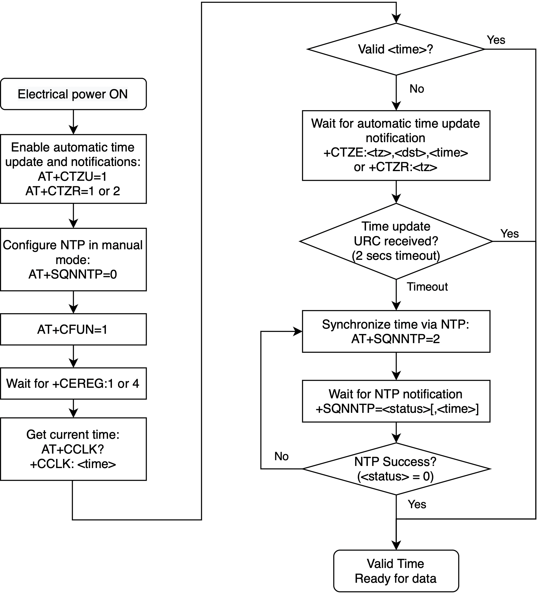
Network Service Commands
4G LTE Band Selection: AT+SQNBANDSEL
| Mode | LTE-M – NBIoT |
| Type | Synchronous |
| Prerequisite | – |
| Time-out | 300 ms |
| Persistency | Reboot Persistent |
Syntax
| Command | Possible Response(s) |
|---|---|
| AT+SQNBANDSEL=<rat>,<operator>,<bandList> | OK |
| AT+SQNBANDSEL? | +SQNBANDSEL:<rat1>,<operator1>,<bandList>
|
| AT+SQNBANDSEL=? |
|
Description
This command enables the user to specify a list of 4G LTE bands the modem is allowed to use for different Radio Access Technologies (RATs) during all cell search operations (initial scanning, cell drop scanning, cell reselection, handover, etc.) for identified <rat> and <operator>. New configuration is saved in non-volatile memory and applied at next device registration to network.
For a given pair of <rat> and <operator>, the list of enabled bands is given by the <bandList> parameter containing comma-separated list of LTE band numbers as defined by 3GPP standard TS 36.101 (4G). Any LTE band not part of <bandList> is considered as deactivated.
<rat> and <operator> mode is defined
as:
standard: equal to device’s supported bands as declared in the device’s bootromMNO/MVNO: list of bands enabled by carrier
Trying to configure a <bandList> containing band(s) not supported in the product
variant causes the AT command to reject the configuration request and respond with an
ERROR message.
The test command reports the list of supported <rat> and <operator> as well as the list of 4G LTE bands supported by the device (Hardware capabilities).
The read command reports the list of authorized band configuration per <rat> and <operator>.
- This AT command should be used only to limit the bands to be scanned compared to default configuration.
- The number of bands that can enabled is limited to the maximum number of bands that can be read
by
AT+SQNBANDSEL=?. Additional bands above this number will be ignored. - Changing the list of bands for a RAT different from what the module currently operates in
returns
ERROR. To change the RAT, see AT+SQNMODEACTIVE.
Defined Values
- rat
- Integer: 0 or 1. Radio Access Technology.
- operator
- String. Operator mode.
- bandList
- String. List of authorized LTE bands, comma separated.
Allow Partial Enabling/Disabling of CEREG URC: AT+SQNCEREGSELECT
| Mode | LTE-M – NBIoT |
| Type | Synchronous |
| Prerequisite | – |
| Time-out | 300 ms |
| Persistency | Reboot Persistent |
Syntax
| Command | Possible Response(s) |
|---|---|
| AT+SQNCEREGSELECT=<n>,<stat> | OK or ERROR |
| AT+SQNCEREGSELECT? | +SQNCEREGSELECT: (list of enabled <stat>)
|
Description
While the AT+CEREG command allows global
activation and deactivation of the +CEREG URC, it is not possible to cherry-pick
specific <stat> values. AT+SQNCEREGSELECT offers a fine-grained
activation/deactivation of +CEREG at the <stat> level.
If +CEREG notifications are disabled by AT+CEREG=0, no +CEREG URC is emitted, irrespective of any
AT+SQNCEREGSELECT setting. If, on the contrary, +CEREG
notifications have been allowed by a prior call to AT+CEREG=n with n ≠ 0, then only those notifications enabled with
AT+SQNCEREGSELECT are raised.
AT+SQNCEREGSELECT settings persist at reboot and over upgrades.
Defined Values
- n
- Integer: 0 or 1. Enable (1) or disable (0) the
+CEREGURC for the given <stat>. - stat
- Integer: 0..10 or 80. Indicates the EPS registration status.
AT+SQNCEREGSELECT?
+SQNCEREGSELECT:0,1,2,3,4,5,6,7,8,9,10,80
EPS Network Registration Status: AT+CEREG
| Mode | LTE-M – NBIoT |
| Type | Synchronous |
| Prerequisite | – |
| Time-out | 300 ms |
| Persistency | Reboot Persistent |
Syntax
| Command | Possible Response(s) |
|---|---|
| AT+CEREG=<n> | OK or +CME ERROR: <err> |
| AT+CEREG? | When <n>=0, 1, 2 or 3 and command successful: |
| AT+CEREG=? |
|
Description
This command controls the presentation of the unsolicited result code
+CEREG: <stat> when <n>=1 and
there is a change in the MT's EPS network registration status in E-UTRAN, or the
unsolicited result code +CEREG:
<stat>[,[<tac>],[<ci>],[<AcT>]] when
<n>=2 and there is a change of the network cell in
E-UTRAN. The parameters <AcT>, <tac>
and <ci> are sent only if available.
The value <n>=3 further extends the unsolicited result code with [,<cause_type>,<reject_cause>], when available, when the value of <stat> changes.
+CEREG URCs presented on the other UARTs.See also Mobile Termination Error Result Code: +CME ERROR for <err> values. The read command returns the status of the result code presentation and an integer <stat> which tells whether the network has currently indicated the registration of the MT. Location information elements <tac>, <ci> and <AcT>, if available, are returned only when <n>=2 and the MT is registered on the network.
The parameters [,<cause_type>,<reject_cause>], if available, are returned when <n>=3.
The test command returns values supported as a compound value.
Defined Values
- n
- Integer: 0..5.
- stat
- Integer: 0..10 or 80. Indicates the EPS registration status.
- tac
- String. Two byte tracking area code in hexadecimal format (e.g. "00C3" equals 195 in decimal).
- ci
- String. Four byte E-UTRAN cell ID in hexadecimal format
- AcT
- Integer: 0..9. The parameter sets/shows the access technology of the serving cell.
- cause_type
- Integer: 0 or 1. Indicates the type of <reject_cause>.
- reject_cause
- Integer. contains the cause of the failed registration. The value is of type as defined by <cause_type>.
- Active-Time
- String. Single byte in an 8 bit format. Indicates the Active Time
value (T3324) allocated to the UE in E-UTRAN. The Active Time value
is coded as one byte (octet 3) of the GPRS Timer 2 information
element coded as bit format (e.g.
"00100100"equals 4 minutes). For the coding and the value range, see the GPRS Timer 2 IE in 3GPP TS 24.008 [8] Table 10.5.163/3GPP TS 24.008. See also 3GPP TS 23.682 [149] and 3GPP TS 23.401 [82]. - Periodic-TAU
- String. Single byte in an 8 bit format. Indicates the extended
periodic TAU value (T3412) allocated to the UE in E-UTRAN. The
extended periodic TAU value is coded as one byte (octet 3) of the
GPRS Timer 3 information element coded as bit format (e.g.
"01000111"equals 70 hours). For the coding and the value range, see the GPRS Timer 3 IE in 3GPP TS 24.008 [8] Table 10.5.163a/3GPP TS 24.008. See also 3GPP TS 23.682 [149] and 3GPP TS 23.401 [82].
Forward Network Reject/Error Codes : AT$ARMEE, $ARME ERROR
| Mode | LTE-M – NBIoT |
| Type | Synchronous |
| Prerequisite | ATT Operator Mode |
| Time-out | 300 ms |
| Persistency | Not Reboot Persistent |
Syntax
| Command | Possible Response(s) |
|---|---|
| AT$ARMEE=[<n>] | OK |
| AT$ARMEE? | $ARMEE: <n>
|
| AT$ARMEE=? | $ARMEE: (list of supported
<n>s)
|
| URC | $ARME ERROR: <type>,<err> |
Description
This command disables or enables the use of the URC $ARME ERROR :<type>,
<err> as an indication of an error relating to the functionality of the UE. When
enabled, the URC $ARME ERROR :<type>, <err> is returned
when the network sends a reject code or ignores a request from Terminal Adaptor. This command is not
related to the AT+CMEE command.
The Test command returns the values supported as a compound value.
Defined Values
- n
- Integer: 0 or 1. Enable/disable the
$ARME ERROR :<type>,<err> URC.
The $ARME ERROR URC
When enabled (AT$ARMEE=1), this URC is sent if the network sends a reject code or
ignores a request from the Terminal Adaptor.
| <type> | <err> |
|---|---|
| ‘01’ - MM Reject code is received during an MM procedure | See 3GPP TS 24.008, 10.5.3.6 Reject Cause |
| ‘02’ - CM Reject code is received during a CM procedure | See 3GPP TS 24.008, 10.5.3.6 Reject Cause |
| ‘03’ - GMM Reject code is received during a non-combined GMM procedure for GPRS services | See 3GPP TS 24.008, 10.5.5.14 GMM Cause |
| ‘04’ - SM Reject is received | See 3GPP TS 24.008, 10.5.6.6 |
| ‘05’ - GMM reject code is received during a combined GMM procedure for non-GPRS services | See 3GPP TS 24.008, 10.5.5.14 GMM Cause |
| ‘06’ - GMM reject code is received during a combined GMM procedure for GPRS and non- GPRS services | See 3GPP TS 24.008, 10.5.5.14 GMM Cause |
| ‘07’ - EMM reject code is received for a non-combined EMM procedure for EPS services | See 3GPP TS 24.301, EMM Cause |
| ‘08’ - EMM reject code is received during a combined procedure for non-EPS services | See 3GPP TS 24.301, EMM Cause |
| ‘09’ - EMM reject code is received during a combined procedure for EPS and non-EPS services | See 3GPP TS 24.301, EMM Cause |
| ‘0A’ - ESM reject code is received during an ESM procedure | |
| ‘0B’-‘FF’ - (RFU) Reserved for Future Use | See 3GPP TS 24.301, 9.9.4.4 |
Handover configuration: AT+SQNHOCFG
| Mode | LTE-M |
| Type | Synchronous |
| Prerequisite | – |
| Time-out | 300 ms |
| Persistency | Reboot Persistent |
Syntax
| Command | Possible Response(s) |
|---|---|
| AT+SQNHOCFG=<rat>,<operator>,<enable> |
|
| AT+SQNHOCFG? |
|
| AT+SQNHOCFG=? |
|
Description
This command is used to read and configure handover (intra- and inter- frequency) behaviour. It is
possible to configure Radio Access Technologies (<rat>s) and identified
<operator> (Note: Available <operator> names correspond
to names as defined in AT+SQNCTM).
The read command reports handover <enable> state per <rat> and <operator>, one {<rat>; <operator>} combination per line, sorted by <rat>, then <operator>. By default, handover feature activation state is defined in pre-provisioned <operator> profiles, driven by operator specific requirements.
The commands modifies the handover configuration for a given <rat> and <operator>. Typically, handover deactivation may be desirable to optimize the modem connection efficiency in case of repeated short connectivity periods needed for small data reporting. In such scenario, the modem can be considered as a static device, and handover are counterproductive for short data sessions, requiring extra activity, thus worsening the power consumption in return for no perceptible gain.
Trying to modify an invalid <rat> and/or <operator> results
in the AT command denying the configuration request and returning ERROR.
"standard" operator. Any attempts to change the configuration of another
operator is rejected.This configuration is stored in non-volatile memory, it survives device reboots and software upgrades.
Changes are effective at the next reconnection to the network (AT+CFUN=1).
See also Mobile Termination Error Result Code: +CME ERROR for <err> values.
Defined Values
- rat
- Integer: 0 or 1.
Table 172. RAT Value RAT 0 Cat. M1 1 Cat. NB1 - operator
- String: Operational mode.
Table 173. Operator Value Mode "standard" Standard 3GPP mode "3gpp-conformance" Standard 3GPP mode tailored to conformance tests "operator-name" Operation mode as defined by the specific supported operator "operator-name" - enable
- Integer: 0 or 1. Handover enable.
Table 174. Enable Value Handover mode 0 No handover 1 Handover enabled
Highest priority EARFCN selection: AT+SQNEARFCNSEL
| Mode | LTE-M – NBIoT |
| Type | Synchronous |
| Prerequisite | Prior call to AT+CFUN=1 to activate |
| Time-out | 300 ms |
| Persistency | Reboot Persistent |
Syntax
| Command | Possible Response(s) |
|---|---|
| AT+SQNEARFCNSEL=<rat>,<operator>,<earfcnList> |
OK or ERROR
|
| AT+SQNEARFCNSEL? |
|
| AT+SQNEARFCNSEL=? |
+SQNEARFCNSEL:
(list of supported <rat>s),
(list of supported <operator>s)
|
Description
The command specifies or updates the list of the highest priority EARFCN for a given Radio Access
Technologies (<rat>) and <operator>. An empty
<earfcnList> argument (i.e. "") resets the list of the
highest priority EARFCN to its factory default.
The read command returns the list of the highest priority EARFCN per <rat> and <operator>, one {<rat>; <operator>} combination per line, sorted by <rat>, then <operator>.
"3gpp-conformance" profile
cannot be modified: any attempt to do so is rejected and returns ERROR.ERROR.ERROR.Defined Values
- rat
- Integer: 0 or 1.
Table 175. RAT Value RAT 0 Cat. M1 1 Cat. NB1 - operator
- String: Operational mode.
Table 176. Operator Value Mode "standard" Standard 3GPP mode "3gpp-conformance" Standard 3GPP mode tailored to conformance tests "operator-name" Operation mode as defined by the specific supported operator "operator-name" - earfcnList
- String. Comma separated list of the highest priority EARFCN.
PLMN Selection: AT+COPS
| Mode | LTE-M – NBIoT |
| Type | Synchronous |
| Prerequisite | Prior call to AT+CFUN=1 |
| Time-out | Network Dependent |
| Persistency | See below |
Syntax
| Command | Possible Response(s) |
|---|---|
| AT+COPS=[<mode>[,<format>[,<oper> [,<AcT>]]]] | OK or +CME ERROR: <err> |
| AT+COPS? |
|
| AT+COPS=? |
|
Description
This command attempts to select and register the MT on the operator
network using the SIM/USIM card installed in the currently selected card
slot.<mode> indicates whether the selection is done
automatically by the MT or is forced to operator <oper>
(whose id is given in format <format>) using a certain
access technology, indicated in <AcT>. If the selected
operator is not available, no other operator is selected (except if
<mode>=4). If the selected access technology is not
available, then the same operator is selected using an other access technology.
The selected operator name format applies to further read commands
(AT+COPS?) also. <mode>=2 forces an
attempt to unregister from the network. The selected mode affects to all further
network registration (e.g. after <mode>=2, MT is
unregistered until <mode>=0 or 1 is selected). This
command should be abortable when registration/de-registration attempt is made.
CEREG URCs will be received
as the module registers/deregisters from the network.
See also Mobile Termination Error Result Code: +CME ERROR for <err> values.
The read command returns the current mode, the currently selected operator and the current Access Technology. If no operator is selected, <format>, <oper> and <AcT> are omitted.
The test command returns a set of five parameters, each representing an operator present in the network. A set consists of an integer indicating the availability of the operator <stat>, long and short alphanumeric format of the name of the operator, numeric format representation of the operator and access technology. If any of the formats are unavailable, the field is empty. The list of operators is in order: home network, networks referenced in SIM or active application in the UICC in the following order: HPLMN selector, User controlled PLMN selector, Operator controlled PLMN selector and PLMN selector (in the SIM or GSM application), and other networks.
It is recommended (although optional) that after the operator list TA returns lists of supported <mode>s and <format>s. These lists shall be delimited from the operator list by two commas.
The access technology selected parameters, <AcT>, should only be used in terminals capable to register to more than one access technology. Selection of <AcT> does not limit the capability to cell reselections, even though an attempt is made to select an access technology, the phone may still re-select a cell in another access technology.
(CFUN=1).Defined Values
- mode
- Integer: 0, 1, 2, 3 or 4.
- format
- Integer: 0, 1 or 2.
- oper
- String. <format> indicates if the format is alphanumeric or numeric; long alphanumeric format can be upto 16 characters long and short format up to 8 characters (refer GSM MoU SE.13 [9]); numeric format is the Location Area Identification number (refer 3GPP TS 24.008 [8] sub-clause 10.5.1.3) which consists of a three BCD digit country code coded as in ITU T Recommendation E.212 [10] Annex A, plus a two BCD digit network code, which is administration specific; returned <oper> shall not be in BCD format, but in IRA characters converted from BCD; hence the number has structure: (country code digit 3)(country code digit 2)(country code digit 1)(network code digit 3)(network code digit 2)(network code digit 1).
- stat
- Integer: 0, 1, 2 or 3.
- AcT
- Integer: 0..9. The parameter sets/shows the access technology selected.
- 3GPP TS 44.060 [71] specifies the System Information messages which give the information about whether the serving cell supports EGPRS.
- 3GPP TS 25.331 [74] specifies the System Information blocks which give the information about whether the serving cell supports HSDPA or HSUPA.
- 3GPP TS 44.018 [156] specifies the EC-SCH INFORMATION message which, if present, indicates that the serving cell supports EC-GSM-IoT.
- 3GPP TS 36.331 [86] specifies the System Information blocks which give the information about whether the serving cell supports NB-IoT, which corresponds to E-UTRAN (NB-S1 mode).
Preferred PLMN List: AT+CPOL
| Mode | LTE-M – NBIoT |
| Type | Synchronous |
| Prerequisite | AT+CFUN=1 or 4. SIM card present |
| Time-out | Depends on SIM |
| Persistency | Reboot Persistent (SIM write) |
Syntax
| Command | Possible Response(s) |
|---|---|
AT+CPOL=[[<index>][, <format>[,<oper> |
|
| AT+CPOL? |
|
| AT+CPOL=? |
|
Description
This command is used to edit the PLMN selector with Access Technology lists in the SIM card or active application in the UICC (GSM or USIM).
- MT can also update the User controlled PLMN selector with Access Technology
EFPLMNwAcT, automatically when new networks are selected. - The Operator controlled PLMN selector with Access Technology
EFOPLMNwAcT, can only be written if the write access condition in the USIM has been previously verified.
Read command returns all used entries from the USIM list of preferred PLMNs, previously selected by the command AT+CPLS, with the Access Technologies for each PLMN in the list.
Test command returns the whole index range supported by the SIM.
See also Mobile Termination Error Result Code: +CME ERROR for
<err> values.
Defined Values
- indexn
- Integer. The order number of operator in the USIM preferred operator list
- format
- Integer: 0, 1 or 2.
- opern
- String. <format> indicates if the format is alphanumeric or numeric (see PLMN Selection: AT+COPS)
- GSM_AcTn
- Integer: 0 or 1. GSM access technology
- GSM_Compact_AcTn
- Integer: 0 or 1. GSM compact access technology
- UTRAN_AcTn
- Integer: 0 or 1. UTRAN access technology
- E-UTRAN_AcTn
- Integer: 0 or 1. E-UTRAN access technology
Read Operator Names: AT+COPN
| Mode | LTE-M – NBIoT |
| Type | Synchronous |
| Prerequisite | – |
| Time-out | 300 ms |
| Persistency | N/A |
Syntax
| Command | Possible Response(s) |
|---|---|
| AT+COPN |
|
| AT+COPN=? | OK |
Description
This command returns the list of operator names from the MT. Each operator code <numericn> that has an alphanumeric equivalent <alphan> in the MT memory is returned.
See also Mobile Termination Error Result Code: +CME ERROR for <err> values.
Defined Values
- numericn
- String. Operator id in numeric format (see PLMN Selection: AT+COPS).
- alphan
- String. Operator id in long alphanumeric format (see PLMN Selection: AT+COPS).
Read the Home PLMN: AT+SQNHPLMN
| Mode | LTE-M – NBIoT |
| Type | Synchronous |
| Prerequisite | AT+CFUN=1 |
| Time-out | 300 ms |
| Persistency | N/A |
Syntax
| Command | Possible Response(s) |
|---|---|
| AT+SQNHPLMN? |
|
Description
This command reads the HPLMN.
Defined Values
- num_oper
- Numeric format. The GSM Location Area Identification number (refer to 3GPP TS 24.008 [8] sub-clause 10.5.1.3). Country code with three BCD digits coded as in ITU-T Recommendation E.212 [10] Annex A, plus a two BCD digit network code, which is administration specific.
- short_oper
- String. Short alphanumeric format of the operator name: up to 8 characters (refer to GSM MoU SE.13 [9]).
- long_oper
- String. Long alphanumeric format of the operator name, up to 16 characters.
Example
AT+SQNHPLMN?
+SQNHPLMN: "00101","TEST","Aeroflex"
OK
Scanning Loop Counter: AT+SQNSEARCHSTEP
| Mode | LTE-M – NBIoT |
| Type | Synchronous |
| Prerequisite | – |
| Time-out | 300 ms |
| Persistency | Not Reboot Persistent |
Syntax
| Command | Possible Response(s) |
|---|---|
| AT+SQNSEARCHSTEP=<enable> | OK |
| AT+SQNSEARCHSTEP? |
|
| AT+SQNSERACHSTEP=? |
|
| URC |
|---|
+SQNSEARCHSTEP: <loop_iteration> |
Description
When this command is used with <enable> = 1, the device sends a URC each time it completes a scanning loop over the configured bands, until it enters the infinite scanning step.
Occasionally, on reception of Attach Reject, the +SQNSEARCHSTEP URC might not be sent
at all. This Attach Reject condition can be checked analysing the +CEREG URC.
If a cell is found, but the modem denies attachment following SIB (System Information Block) decoding,
+SQNSEARCHSTEP URC value can be reset to 1.
The maximum value the URC can reach before entering the infinite loop is set in the scanner configuration (see 4G LTE Band Selection: AT+SQNBANDSEL and Highest priority EARFCN selection: AT+SQNEARFCNSEL commands).
Defined values
- enable
- Integer: 0 or 1. Activate or deactivate the URC.
Table 186. n enable URC 0 Disable the URCs (default). 1 Enable the URC. URC sending stops when the device enters the infinite scanning loop. - loop_iteration
- Integer: 1..255. Current number of loops already performed.
Examples
ATC+CFUN=1
OK
+CEREG: 2
+CEREG: 4
+CEREG: 2
+SQNSEARCHSTEP: 1
+SQNSEARCHSTEP: 2
+SQNSEARCHSTEP: 3
...
+SQNSEARCHSTEP: 131
+SQNSEARCHSTEP: 132  ==> No cell found, proceed to infinite scannning loop
loop.

AT+CFUN=1
OK
+CEREG: 2
+SQNSEARCHSTEP: 1
+CEREG: 4
+CEREG: 2
+SQNSEARCHSTEP: 2
+SQNSEARCHSTEP: 3
+CEREG: 3,,,,0,15  ==> Attach Reject
+CEREG: 80
+CEREG: 2
+SQNSEARCHSTEP: 1

AT+CFUN=1
OK
+CEREG: 2
+SQNSEARCHSTEP: 1
+CEREG: 4
+CEREG: 2
+SQNSEARCHSTEP: 2
+SQNSEARCHSTEP: 3
+SQNSEARCHSTEP: 1  ==>  Cell found but not suitable, restart scanning
+CEREG: 4
+CEREG: 2
+SQNSEARCHSTEP: 2
+SQNSEARCHSTEP: 3
+SQNSEARCHSTEP: 1
Select Wireless Network: AT+WS46
| Mode | LTE-M – NBIoT |
| Type | Synchronous |
| Prerequisite | – |
| Time-out | 300 ms |
| Persistency | Not Reboot Persistent |
Syntax
| Command | Possible Response(s) |
|---|---|
| AT+WS46=<n> |
|
| AT+WS46? | <n> |
| AT+WS46=? | [(list of supported <n>s)] |
Description
Set command selects the WDS side stack <n> to be used by the TA. Read command shows current setting and test command displays side stacks implemented in the TA.
Defined Values
- n (read mode)
- Integer (see below). The values in <n> for the read command are mutually exclusive. A single value is always returned.
- n (set mode)
- Integer: 12 (see below). Refer PCCA STD 101 [17] for other values.
Selection of Preferred PLMN List: AT+CPLS
| Mode | LTE-M – NBIoT |
| Type | Synchronous |
| Prerequisite | AT+CFUN=1 or 4. SIM card present |
| Time-out | 300 ms |
| Persistency | Not Reboot Persistent |
Syntax
| Command | Possible Response(s) |
|---|---|
| AT+CPLS=<list> | OK or +CME ERROR: <err> |
| AT+CPLS? |
|
| AT+CPLS=? |
|
Description
This command selects one PLMN selector with Access Technology list in the SIM card or active application in the UICC (GSM or USIM), that is used by Preferred PLMN List: AT+CPOL command.
The read command returns the selected PLMN selector list from the SIM/USIM.
The test command returns the whole index range supported lists by the SIM/USIM.
See also Mobile Termination Error Result Code: +CME ERROR for <err> values.
Defined Values
- list
- Integer: 0, 1 or 2.
Subscriber Number: AT+CNUM
| Mode | LTE-M – NBIoT |
| Type | Synchronous |
| Prerequisite | AT+CFUN=1 or 4. SIM card present |
| Time-out | 300 ms |
| Persistency | N/A |
Syntax
| Command | Possible Response(s) |
|---|---|
| AT+CNUM |
|
| AT+CNUM=? | OK |
Description
Action command returns the MSISDNs related to the subscriber (this information can be stored in the SIM/UICC or in the MT). When storing information in the SIM/UICC, if the currently selected card slot contains a SIM card or a UICC with an active GSM application, the information is stored in the EFMSISDN under DFTelecom. If the currently selected card slot contains a UICC with an active USIM application, the information is stored in the EFMSISDN under ADFUSIM). If subscriber has different MSISDN for different services, each MSISDN is returned in a separate line.
See also Mobile Termination Error Result Code: +CME ERROR for <err> values.
Defined Values
- alphax
- String. Associated with <numberx>; the character set should be the one selected with command Select TE Character Set: AT+CSCS.
- numberx
- String. Phone number in the format specified by <typex>.
- typex
- Integer. Type of address octet (see 3GPP TS 24.008 [8] sub-clause 10.5.4.7)
- speed
- As defined in sub-clause 6.7
- service
- Integer: 0..5. Service related to the phone number.
- itc
- Integer: 0 or 1. Information transfer capability.
Attach Backoff Reason: AT+SQNATBOFF
| Mode | LTE-M – NBIoT |
| Type | Synchronous |
| Prerequisite | - |
| Time-out | 300 ms |
| Persistency | Reboot Persistent |
Syntax
| Command | Possible Response(s) |
|---|---|
| AT+SQNATBOFF=<enable> | OK |
| AT+SQNATBOFF=? |
|
| URC | +SQNATBOFF:
<reason>,<wait_time> |
Description
When the UE is unable to attach to the network due to a 3GPP-mandated timer (such as T3402) or due to a specific attach protection mechanism, the host currently is not informed of the reason. To improve power efficiency and system transparency, this URC notifies the host that attach attempts are blocked for a certain period of time.
For backwards compatibility reasons, this URC is disabled by default.
Defined Values
- enable
- Integer: 0 or 1. Enables (1) or disables (0, default) the URC.
- reason
- Integer: 1..3. Cause of failure:
Table 192. reason 1 T3402 timer running (3GPP). 2 VZW permanent failure protection active. 3 Other 3GPP attach-block condition. - wait_time
- Integer. Estimated time before next attempt could be successful. 0 if no estimation is available.
Check and Clean MRU: AT+SQNMRU
| Mode | LTE-M – NBIoT |
| Type | Synchronous |
| Prerequisite | CFUN 0 state |
| Time-out | 300 ms |
| Persistency | N/A |
Syntax
| Command | Possible Response(s) |
|---|---|
| AT+SQNMRU=<clear> |
|
| AT+SQNMRU? |
|
| AT+SQNMRU=? |
|
Description
This command erases the Most Recently Used cell stored in Module. If no MRU exists, the
command does nothing and returns OK.
The read command returns the E-UTRAN Cell Id of the most recently used cell. If no MRU info is
available, the command returns 0.
The set command is available only in +CFUN 0 mode. The read command is available in
both +CFUN 0 and +CFUN 1 mode.
Defined Values
- clear
- Integer: 0. Erases MCU info and returns
OK. All other values returnERROR. - cid
-
Integer in hexadecimal format. Either:
- 0 if no information available.
- Or the 28-bit E-UTRAN Cell Identity as advertised in SIB1 (System Information Block Type 1) of MRU cell.
Packet Domain Related Commands
Define EPS Quality Of Service: AT+CGEQOS
| Mode | LTE-M – NBIoT |
| Type | Synchronous |
| Prerequisite | – |
| Time-out | 1 s |
| Persistency | Not Reboot Persistent |
Syntax
| Command | Possible Response(s) |
|---|---|
|
AT+CGEQOS=[<cid>[,<QCI> |
OK or +CME ERROR: <err> |
| AT+CGEQOS? |
|
| AT+CGEQOS=? | +CGEQOS:
(range of supported <cid>s),(list of supported <QCI>s),(list of supported <DL_GBR>s),(list of supported <UL_GBR>s),(list of supported <DL_MBR>s),(list of supported <UL_MBR>s)
|
Description
This command allows the TE to specify the EPS Quality of Service parameters <cid>, <QCI>, <DL_GBR> and <UL_GBR> and <DL_MBR> and <UL_MBR> for a PDP context or Traffic Flows (see 3GPP TS 24.301 [83] and 3GPP TS 23.203 [85]). When in UMTS/GPRS the MT applies a mapping function to UTMS/GPRS Quality of Service.
See also Mobile Termination Error Result Code: +CME ERROR for <err> values.
A special form of the set command, AT+CGEQOS=<cid>,
causes the values for context number <cid> to become undefined.
The read command returns the current settings for each defined QoS.
The test command returns the ranges of the supported parameters.
Defined Values
- cid
- Integer. Specifies a particular EPS Traffic Flows definition in EPS and a PDP Context definition in UMTS/GPRS (see the Define PDP Context: AT+CGDCONT and Define Secondary PDP Context: AT+CGDSCONT commands).
- QCI
- Integer: 0..254. Specifies a class of EPS QoS (see 3GPP TS 24.301 [83]).
- DL_GBR
- Integer. Indicates DL GBR in case of GBR QCI. The value is in kbit/s. This parameter is omitted for a non-GBR QCI (see 3GPP TS 24.301 [83]).
- UL_GBR
- Integer. Indicates UL GBR in case of GBR QCI. The value is in kbit/s. This parameter is omitted for a non-GBR QCI (see 3GPP TS 24.301 [83]).
- DL_MBR
- Integer. Indicates DL MBR in case of GBR QCI. The value is in kbit/s. This parameter is omitted for a non-GBR QCI (see 3GPP TS 24.301 [83]).
- UL_MBR
- Integer. Indicates UL MBR in case of GBR QCI. The value is in kbit/s. This parameter is omitted for a non-GBR QCI (see 3GPP TS 24.301 [83]).
Define PDP Context Authentication Parameters: AT+CGAUTH
| Mode | LTE-M – NBIoT |
| Type | Synchronous |
| Prerequisite | – |
| Time-out | 300 ms |
| Persistency | Reboot Persistent |
Syntax
| Command | Possible Response(s) |
|---|---|
|
AT+CGAUTH=<cid>[,<auth_prot> |
|
| AT+CGAUTH? |
[ |
| AT+CGAUTH=? |
+CGAUTH: (range of supported <cid>s),(
list of supported <auth_prot>s),(range of supported <userid>s),(range of supported <password>s)
|
Description
This command allows the TE to specify authentication parameters for a PDP context identified by the (local) context identification parameter <cid> used during the PDP context activation and the PDP context modification procedures. Since the <cid> is the same parameter that is used in the AT+CGDCONT and AT+CGDSCONT commands, Define PDP Context Authentication Parameters: AT+CGAUTH can be thought of as an extension to these commands.
See also Mobile Termination Error Result Code: +CME ERROR for <err> values.
The read command returns the current settings for each defined context.
The test command returns values supported as a compound value.
Defined Values
- cid
- Integer. Specifies a particular PDP context definition (see the Define PDP Context: AT+CGDCONT and Define Secondary PDP Context: AT+CGDSCONT commands).
- auth_prot
- Integer: 0, 1 or 2. Authentication protocol used for this PDP context.
- userid
- String. User name for access to the IP network.
- password
- String. Password for access to the IP network.
Define PDP Context: AT+CGDCONT
| Mode | LTE-M – NBIoT |
| Type | Synchronous |
| Prerequisite | Module must not be attached (+CEREG ≠ 1 or 5) |
| Time-out | 300 ms |
| Persistency | Reboot Persistent |
Syntax
| Command | Possible Response(s) |
|---|---|
AT+CGDCONT=<cid> |
OK or ERROR or +CME ERROR: <err> |
| AT+CGDCONT? | [ |
| AT+CGDCONT=? |
|
Description
This command specifies PDP context parameter values for a PDP context identified by the (local) context identification parameter, <cid> and also allows the TE to specify whether the security protected transmission of ESM information is requested, because the PCO can include information that requires ciphering. There can be other reasons for the UE to use security protected transmission of ESM information, e.g. if the UE needs to transfer an APN. The number of PDP contexts that may be in a defined state at the same time is given by the range returned by the test command.
For EPS the PDN connection and its associated EPS default bearer is identified herewith.
A special form of this command, AT+CGDCONT=<cid> causes the
values for context number <cid> to become undefined. This
only works for <cid>s other than 1.
AT+CGDCONT. If the initial PDP context is supported,
AT+CGDCONT=0 resets context number 0 to its particular
default settings.The read command returns the current settings for each defined context.
The test command returns values supported as a compound value. If the MT supports several PDP types, <PDP_type>, the parameter value ranges for each <PDP_type> are returned on a separate line.
Defined Values
- cid
- Integer. Specifies a particular PDP context definition. The parameter is local to the TE-MT interface and is used in other PDP context-related commands. The range of permitted values (minimum value = 1 or if the initial PDP context is supported (see sub-clause 10.1.0), minimum value = 0) is returned by the test form of the command.
- PDP_type
- String. Specifies the type of packet data protocol.
- APN
- String. A logical name that is used to select the GGSN or the external packet data network.
- PDP_addr
- String. Identifies the MT in the address space applicable to the PDP.
- d_comp
- Integer: 0, 1, 2 or 3. Controls PDP data compression (applicable for SNDCP only) (refer 3GPP TS 44.065 [61]).
- h_comp
- Integer: 0..4. Controls PDP header compression (refer 3GPP TS 44.065 [61] and 3GPP TS 25.323 [62]).
- IPv4AddrAlloc
- Integer: 0 or 1. Controls how the MT/TA requests to get the IPv4 address information.
- request_type
- Integer: 0..4. Indicates the type of PDP context activation request for the PDP context, see 3GPP TS 24.301 [83] (sub-clause 6.5.1.2) and 3GPP TS 24.008 [8] (sub-clause 10.5.6.17). If the initial PDP context is supported (see sub-clause 10.1.0) it is not allowed to assign <cid>=0 for emergency bearer services. According to 3GPP TS 24.008 [8] (sub-clause 4.2.4.2.2 and sub-clause 4.2.5.1.4) and 3GPP TS 24.301 [83] (sub-clause 5.2.2.3.3 and sub-clause 5.2.3.2.2), a separate PDP context must be established for emergency bearer services.
- P-CSCF_discovery
- Integer: 0 or 1. Influences how the MT/TA requests to get the P-CSCF address, see 3GPP TS 24.229 [89] annex B and annex L.
- IM_CN_Signalling_Flag_Ind
- Integer: 0 or 1. Indicates to the network whether the PDP context is for IM CN subsystem-related signalling only or not.
- NSLPI
- Integer: 0 or 1. Indicates the NAS signalling priority requested for this PDP context.
- securePCO
- Integer: 0 or 1. Specifies if security protected transmission of PCO is requested or not (applicable for EPS only, see 3GPP TS 23.401 [82] sub-clause 6.5.1.2).
- IPv4_MTU_discovery
- Integer: 0 or 1. Influences how the MT/TA requests to get the IPv4 MTU size, see 3GPP TS 24.008 [8] sub-clause 10.5.6.3.
- Local_Addr_Ind
- Integer: 0 or 1. indicates to the network whether or not the MS supports local IP address in TFTs (see 3GPP TS 24.301 [83] and 3GPP TS 24.008 [8] sub-clause 10.5.6.3).
- Non-IP_MTU_discovery
- Integer: 0 or 1. Influences how the MT/TA requests to get the Non-IP MTU size, see 3GPP TS 24.008 [8] sub-clause 10.5.6.3.
- Reliable_Data_Service
- Integer: 0 or 1. Indicates whether the UE is using Reliable Data Service for a PDN connection or not, see 3GPP TS 24.301 [83] and 3GPP TS 24.008 [8] sub-clause 10.5.6.3.
Define Secondary PDP Context: AT+CGDSCONT
| Mode | LTE-M |
| Type | Synchronous |
| Prerequisite | – |
| Time-out | 300 ms |
| Persistency | Not Reboot Persistent |
Syntax
| Command | Possible Response(s) |
|---|---|
|
AT+CGDSCONT=[<cid>, <p_cid> |
OK or ERROR |
| AT+CGDSCONT? |
[ OK |
| AT+CGDSCONT=? | +CGDSCONT: (range of supported <cid>s),(list of <p_cid>s for active primary contexts),(list of supported
<d_comp>s),(list of supported <h_comp>s),(list of supported
<IM_CN_Signalling_Flag_Ind>s)
|
Description
This command specifies PDP context parameter values for a Secondary PDP context identified by the (local) context identification parameter, <cid>. The number of possible PDP contexts in a given state at the same time is returned by the test command.
In EPS, the command is used to define traffic flows.
AT+CGDSCONT=<cid> causes the values for
context number <cid> to become undefined. The test command returns values supported as a compound value.
Defined Values
- cid
- Integer: PDP context definition. The parameter is local to the TE-MT interface and is used in other PDP context-related commands. The range of permitted values (minimum value = 1) is returned by the test command.
- p_cid
- Integer: Specifies a particular PDP context definition which has been specified by use of the AT+CGDCONT command. The parameter is local to the TE-MT interface. The list of permitted values is returned by the test form of the command.
- d_comp
- Integer: 0, 1, 2 or 3. Controls PDP data compression (applicable for SNDCP only) (refer 3GPP TS 44.065 [61])
- h_comp
- Integer: 0..4. Controls PDP header compression (refer 3GPP TS 44.065 [61] and 3GPP TS 25.323 [62])
- IM_CN_Signalling_Flag_Ind
- Integer: 0 or 1. Indicates to the network whether the PDP context is for IM CN subsystem-related signalling only or not.
EPS Quality Of Service Read Dynamic Parameters: AT+CGEQOSRDP
| Mode | LTE-M – NBIoT |
| Type | Synchronous |
| Prerequisite | AT+CFUN = 1 or 4. SIM card present |
| Time-out | 300 ms |
| Persistency | N/A |
Syntax
| Command | Possible Response(s) |
|---|---|
| AT+CGEQOSRDP |
[ |
| AT+CGEQOSRDP=? |
+CGEQOSRDP:(list of <cid>s associated with active
contexts)
|
Description
This command returns the Quality of Service parameters <QCI>, [<DL_GBR> and <UL_GBR>] and [<DL_MBR> and <UL_MBR>] of the active secondary or non secondary PDP context associated to the provided context identifier <cid>.
If the parameter <cid> is omitted, the Quality of Service parameters for all secondary and non secondary active PDP contexts are returned.
The test command returns a list of <cid>s associated with secondary or non secondary active PDP contexts.
Parameters of both network and MT/TA initiated PDP contexts are returned.
Defined Values
- cid
- Integer. Specifies a particular Traffic Flows definition in EPS and a PDP Context definition in UMTS/GPRS (see the Define PDP Context: AT+CGDCONT and Define Secondary PDP Context: AT+CGDSCONT commands).
- QCI
- Integer: 0..254. Specifies a class of EPS QoS (see 3GPP TS 24.301 [83]).
- DL_GBR
- Integer. Indicates DL GBR in case of GBR QCI. The value is in kbit/s. This parameter is omitted for a non-GBR QCI (see 3GPP TS 24.301 [83]).
- UL_GBR
- Integer. Indicates UL GBR in case of GBR QCI. The value is in kbit/s. This parameter is omitted for a non-GBR QCI (see 3GPP TS 24.301 [83]).
- DL_MBR
- Integer. Indicates DL MBR in case of GBR QCI. The value is in kbit/s. This parameter is omitted for a non-GBR QCI (see 3GPP TS 24.301 [83]).
- UL_MBR
- Integer. Indicates UL MBR in case of GBR QCI. The value is in kbit/s. This parameter is omitted for a non-GBR QCI (see 3GPP TS 24.301 [83]).
- DL_AMBR
- Integer. Indicates DL APN aggregate MBR (see 3GPP TS 24.301 [83]). The value is in kbit/s.
- UL_AMBR
- Integer. Indicates UL APN aggregate MBR (see 3GPP TS 24.301 [83]). The value is in kbit/s.
Enter Data State: AT+CGDATA
| Mode | LTE-M – NBIoT |
| Type | Synchronous |
| Prerequisite | AT+CFUN = 1 or 4. SIM card present |
| Time-out | 2 s |
| Persistency | N/A |
Syntax
| Command | Possible Response(s) |
|---|---|
| AT+CGDATA[=<L2P>[,<cid>[,<cid>[,…]]]] |
|
| AT+CGDATA=? | +CGDATA: (list of supported <L2Ps>)
|
Description
This command causes the MT to perform whatever actions are necessary to establish communication between
the TE and the network using one or more Packet Domain PDP types. This may include performing a PS
attach and one or more PDP context activations. If the <L2P> parameter value is
unacceptable to the MT, the MT shall return an ERROR or +CME ERROR
response. Otherwise, the MT issues the intermediate result code CONNECT and enters
V.250 online data state.
AT+CGDATA command in the AT command line are not processed by
the MT. The detailed behaviour after the online data state has been entered is dependent on the PDP type. It is described briefly in 3GPP TS 25.060 [34] and in more detail in 3GPP TS 29.061 [39] and the specifications for the relevant PDPs. PS attachment and PDP context activation procedures may take place prior to or during the PDP start-up if they have not already been performed using the PS Attach or Detach: AT+CGATT and PDP Context Activate or Deactivate: AT+CGACT commands.
If context activation takes place during the PDP start-up, one or more <cid>s can be specified in order to provide the information needed for the context activation request(s).
- The MT may have a priori knowledge. For example, it may implement only one PDP type.
- The command may have provided an <L2P> parameter value.
- The TE may provide a PDP type and/or PDP address to the MT during in the PDP start-up procedure.
- The PDP type must match exactly.
- The PDP addresses are considered to match if they are identical or if either or both addresses are unspecified. For example, a PPP NCP request specifying PDP type = IP and no PDP address would cause the MT to search through the specified context definitions for one with PDP type = IP and any PDP address.
If no <cid> is given or if there is no matching context definition, the MT attempts to activate the context with whatever information is available to it. The other context parameters are set to their default values.
If the activation is successful, data transfer may proceed.
After the data transfer is complete, and the layer 2 protocol termination procedure has completed
successfully, the V.250 command state is re-entered and the MT returns the final result code
OK.
In the event of an abnormal termination or a failure to start up, the V.250 command state is re-entered
and the MT returns the final result code NO CARRIER or, if enabled, +CME
ERROR. Attach, activate and other errors may be reported.
The test command is used for requesting information on the supported layer 2 protocols.
This command may be used in both normal and modem compatibility modes.
Defined Values
- cid
- Integer. This parameter specifies a particular PDP context definition (see Define PDP Context: AT+CGDCONT parameter <cid>).
- L2P
- String: "PPP". Layer 2 Protocol (L2P) to be used between the TE and MT.
Initial PDP Context Activation: AT+CIPCA
| Mode | LTE-M – NBIoT |
| Type | Synchronous |
| Prerequisite | – |
| Time-out | 300 ms |
| Persistency | Not Reboot Persistent |
Syntax
| Command | Possible Response(s) |
|---|---|
| AT+CIPCA=[<n>[,<AttachWithoutPDN>]] |
|
| AT+CIPCA? | +CIPCA: <n>[,<AttachWithoutPDN>]
|
| AT+CIPCA=? | +CIPCA:
(list of supported <n>s),(list of supported <AttachWithoutPDN>s)
|
Description
This command controls whether an initial PDP context (see subclause 10.1.0) is automatically established after the attach procedure when the UE is attached to GERAN or UTRAN RATs, and whether the UE is attached to E-UTRAN with or without a PDN connection.
For <n>≠0, deactivating the last (active) PDP context can lead to a (re)establishment of the initial PDP context. Changing setting of <n> from 0 to 1 triggers an immediate attempt to (re)establish the initial PDP context if no PDP context is active. Changing <n> from 0 to 2, triggers an immediate attempt to (re)establish the initial PDP context if no other PDP context is active and the device is not in roaming mode. The value of <n>=3 applies to E-UTRAN RATs and does not change the setting of PDP context activation in GERAN or UTRAN RATs. Changing <n> never causes a PDP context deactivation.
The read command returns the current setting of the command.
Test command returns the modes supported as compound values.
See also Mobile Termination Error Result Code: +CME ERROR for <err>
values.
Defined Values
- n
- Integer: 0, 1, 2 or 3. Activation of PDP context upon attach.
- AttachWithoutPDN
- 0 or 1. EPS Attach with or without PDN connection.
PDP Context Activate or Deactivate: AT+CGACT
| Mode | LTE-M – NBIoT |
| Type | Synchronous |
| Prerequisite | AT+CFUN=1. SIM card present |
| Time-out | Network dependent |
| Persistency | Not Reboot Persistent |
Syntax
| Command | Possible Response(s) |
|---|---|
| AT+CGACT=[<state>[,<cid>[,<cid>[,…]]]] |
|
| AT+CGACT? |
|
| AT+CGACT=? |
+CGACT: (list of supported <state>s)
|
Description
This command is used to activate or deactivate the specified PDP context(s). After the command has
completed, the MT remains in V.250 command state. If any PDP context is already in the requested
state, the state for that context remains unchanged. If the requested state for any specified
context cannot be achieved, an ERROR or +CME ERROR response is
returned. Extended error responses are enabled by the Report Mobile Termination Error: AT+CMEE command. If the MT is not PS attached when the activation form of the command is
executed, the MT first performs a PS attach and then attempts to activate the specified contexts. If
the attach fails then the MT responds with ERROR or, if extended error responses
are enabled, with the appropriate failure-to-attach error message.
See also Mobile Termination Error Result Code: +CME ERROR for <err> values.
ERROR or, if extended error responses are enabled, a +CME
ERROR. If no <cid>s are specified the command activates or deactivates all defined contexts.
The read command returns the current activation states for all the defined PDP contexts.
Defined Values
- state
- Integer: 0 or 1. Indicates the state of PDP context activation.
- cid
- Integer. Specifies a particular PDP context definition (see the Define PDP Context: AT+CGDCONT and Define Secondary PDP Context: AT+CGDSCONT commands).
PDP Context Modify: AT+CGCMOD
| Mode | LTE-M – NBIoT |
| Type | Synchronous |
| Prerequisite | AT+CFUN=1. SIM card present |
| Time-out | 300 ms |
| Persistency | Not Reboot Persistent |
Syntax
| Command | Possible Response(s) |
|---|---|
| AT+CGCMOD[=<cid>[,<cid>[…]]] | OK or +CME ERROR: <err> |
| AT+CGCMOD=? | +CGCMOD: (list of <cid>s with active
contexts)
|
Description
The execution command is used to modify the specified PDP context (s) with repect to QoS profiles, TFTs and MBS sessions.
After the command
has completed, the MT returns to V.250 online data state. If the requested modification for any specified context cannot be achieved,
an ERROR or +CME ERROR response is returned. Extended error
responses are enabled by the AT+CMEE command.
See also Mobile Termination Error Result Code: +CME ERROR for <err> values.
For EPS, the modification request for an EPS bearer resource will be answered by the network by an EPS bearer modification request. The request must be accepted by the MT before the PDP context is effectively changed. If no <cid>s are specified the activation form of the command modifies all active contexts.
The test command returns a list of <cid>s associated with active contexts.
Defined Values
- cid
- Integer. Specifies a particular PDP context definition (see the Define PDP Context: AT+CGDCONT and Define Secondary PDP Context: AT+CGDSCONT commands).
PDP Context Read Dynamic Parameters: AT+CGCONTRDP
| Mode | LTE-M – NBIoT |
| Type | Synchronous |
| Prerequisite | AT+CFUN=1. SIM card present |
| Time-out | 300 ms |
| Persistency | N/A |
Syntax
| Command | Possible Response(s) |
|---|---|
| AT+CGCONTRDP[=<cid>] |
[ |
| AT+CGCONTRDP=? | +CGCONTRDP:(list of <cid>s associated with activecontexts)
|
Description
This command returns the relevant information (<bearer_id>, <apn>, <local_addr and subnet_mask>, <gw_addr>, <DNS_prim_addr>, <DNS_sec_addr>, <P-CSCF_prim_addr>, <P-CSCF_sec_addr>, <IM_CN_Signalling_Flag> and <LIPA_indication>) for an active, non-secondary PDP context with the context identifier <cid>.
If the MT indicates more than two IP addresses of P-CSCF servers or more than two IP addresses of DNS servers, multiple lines of information per <cid> are returned.
The test command returns a list of <cid>s associated with active, non-secondary contexts.
Defined Values
- cid
- Integer. Specifies a non-secondary PDP context definition. The parameter is local to the TE-MT interface and is used in other PDP context-related commands (see the Define PDP Context: AT+CGDCONT and Define Secondary PDP Context: AT+CGDSCONT commands).
- bearer_id
- Integer. Identifies the bearer, i.e. the EPS bearer in EPS and the NSAPI in UMTS/GPRS.
- apn
- String. A logical name that was used to select the GGSN or the external packet data network.
- local_addr, subnet_mask
- String. IP address and subnet mask of the MT.
The string is given as dot-separated numeric
(0-255) parameters on the form:
"a1.a2.a3.a4.m1.m2.m3.m4"for IPv4 or"a1.a2.a3.a4.a5.a6.a7.a8.a9.a10.a11.a12. a13.a14.a15.a16.m1.m2.m3.m4.m5.m6.m7.m8.m9.m10.m11.m12.m13.m14.m15.m16"for IPv6. - gw_addr
- String. Gateway Address of the MT. The string is given as dot-separated numeric (0-255) parameters.
- DNS_prim_addr
- String. IP address of the primary DNS server.
- DNS_sec_addr
- String. IP address of the secondary DNS server.
- P_CSCF_prim_addr
- String. IP address of the primary P-CSCF server.
- P_CSCF_sec_addr
- String. IP address of the secondary P-CSCF server.
- IM_CN_Signalling_Flag
- Integer: 0 or 1. Tells whether the PDP context is for IM CN subsystem-related signalling only or not.
- LIPA_indication
- Integer: 0 or 1. Indicates that the PDP context provides connectivity using a LIPA PDN connection. This parameter cannot be set by the TE.
- IPv4_MTU
- Integer. IPv4 MTU size in bytes.
- WLAN_offload
- Integer: 0..3. Indicates whether traffic can be offloaded using the specified
PDN connection via a WLAN or not. This refers to bits 1 and 2 of the WLAN
offload acceptability IE as specified in 3GPP TS 24.008 clause 10.5.6.20.
Table 218. WLAN_offload Value Description 0 Offloading the traffic of the PDN connection via a WLAN when in S1 mode or when in Iu mode is not acceptable. 1 Offloading the traffic of the PDN connection via a WLAN when in S1 mode is acceptable, but not acceptable in Iu mode. 2 Offloading the traffic of the PDN connection via a WLAN when in Iu mode is acceptable, but not acceptable in S1 mode. 3 Offloading the traffic of the PDN connection via a WLAN when in S1 mode or when in Iu mode is acceptable. - Local_Addr_Ind
- Integer: 0 or 1. Indicates whether (1) or not (0) the MS and the network support local IP address in TFTs (see 3GPP TS 24.301 and 3GPP TS 24.008 clause 10.5.6.3).
- Non-IP_MTU
- Integer. Non-IP MTU size in bytes.
- Serving_PLMN_rate_control_value
- Integer. Indicates the maximum number of uplink messages the UE is allowed to send in a 6 minute interval. This refers to byte 3 to 4 of the Serving PLMN rate control IE as specified in 3GPP TS 24.301 clause 9.9.4.28.
PS Attach or Detach: AT+CGATT
| Mode | LTE-M – NBIoT |
| Type | Synchronous |
| Prerequisite | AT+CFUN=1. SIM card present |
| Time-out | Network dependent |
| Persistency | Not Reboot Persistent |
Syntax
| Command | Possible Response(s) |
|---|---|
| AT+CGATT=<state> |
|
| AT+CGATT? | +CGATT: <state>
|
| AT+CGATT=? | +CGATT: (list of supported <state>s)
|
Description
This command attaches the MT to, or detach the MT from, the Packet Domain service. After the command has completed, the MT remains in V.250 command state. If the MT is already in the requested state, the command is ignored and the OK response is returned. If the requested state cannot be achieved, an ERROR or +CME ERROR response is returned. Extended error responses are enabled by the Report Mobile Termination Error: AT+CMEE command.
The read command returns the current Packet Domain service state.
Defined Values
- state
- Integer: 0 or 1. Indicates the state of PS attachment.
Packet Domain Event Reporting: AT+CGEREP
| Mode | LTE-M – NBIoT |
| Type | Synchronous / Asynchronous |
| Prerequisite | – |
| Time-out | 300 ms |
| Persistency | Reboot Persistent |
Syntax
| Command | Possible Response(s) |
|---|---|
| AT+CGEREP=[<mode>[,<bfr>]] |
|
| AT+CGEREP? |
|
| AT+CGEREP=? | +CGEREP:
(list of supported <mode>s),(list of
supported<bfr>s)
|
Description
This command enables or disables the unsolicited result codes, +CGEV:
… from MT to TE in the case of certain events occurring in the
Packet Domain MT or the network. <mode> controls the
processing of unsolicited result codes specified within this command.
<bfr> controls the effect on buffered codes when
<mode> 1 or 2 is entered. If a setting is not
supported by the MT, ERROR or +CME ERROR is
returned.
See also Mobile Termination Error Result Code: +CME ERROR for <err> values.
Read command returns the current mode and buffer settings.
The test command returns the modes and buffer settings supported by the MT as compound values.
Defined Values
- mode
- Integer: 0, 1 or 2.
- bfr
- Integer: 0 or 1.
Event Notification URC: +CGEV
- For network attachment, the following unsolicited result codes and the
corresponding events are defined:
+CGEV: NW DETACHThe network has forced a PS detach. This implies that all active contexts have been deactivated. These are not reported separately.
+CGEV: ME DETACHThe mobile termination has forced a PS detach. This implies that all active contexts have been deactivated. These are not reported separately.
- For MT class, the following unsolicited result codes and the
corresponding events are defined:
+CGEV: NW CLASS <class>The network has forced a change of MT class. The highest available class is reported (see
+CGCLASSin 3GPP 25.007 specification). The format of the parameter <class> is given below.+CGEV: ME CLASS <class>The mobile termination has forced a change of MT class. The highest available class is reported (see
+CGCLASSin 3GPP 25.007 specification). The format of the parameter <class> is given below.
- class
-
- A: Class-A mode of operation (A/Gb mode), or CS/PS mode of operation (Iu mode) (highest mode of operation)
- B: Class-B mode of operation (A/Gb mode), or CS/PS mode of operation (Iu mode)
- CG: Class-C mode of operation in PS only mode (A/Gb mode), or PS mode of operation (Iu mode)
- CC: Class-C mode of operation in CS only mode (A/Gb mode), or CS (Iu mode) (lowest mode of operation)
Note:A means that the MT would operate simultaneous PS and CS service;
If the MT is attached to the PS domain when the set command is issued with CC specified, a PS detach shall be performed by the MT.
B means that the MT would operate PS and CS services but not simultaneously in A/Gb mode;
CG means that the MT would only operate PS services;
CC means that the MT would only operate CS services. - For PDP context activation, the following unsolicited result codes and
the corresponding events are defined:
+CGEV: NW PDN ACT <cid>[,<WLAN_Offload>]The network has activated a context. The context represents a Primary PDP context in GSM/UMTS. The <cid> for this context is provided to the TE. The format of the parameter <cid> is found in command Define PDP Context: AT+CGDCONT.
<WLAN_Offload>: Integer: 0..3. Indicates whether traffic can be offloaded using the specified PDN connection via a WLAN or not. This refers to bit 1 (E-UTRAN offload acceptability value) and bit 2 (UTRAN offload acceptability value) in the WLAN offload acceptability IE as specified in 3GPP TS 24.008 [8] sub-clause 10.5.6.20.
Table 222. WLAN_Offload Value Description 0 Offloading the traffic of the PDN connection via a WLAN when in S1 mode or when in Iu mode is not acceptable. 1 Offloading the traffic of the PDN connection via a WLAN when in S1 mode is acceptable, but not acceptable in Iu mode. 2 Offloading the traffic of the PDN connection via a WLAN when in Iu mode is acceptable, but not acceptable in S1 mode. 3 Offloading the traffic of the PDN connection via a WLAN when in S1 mode or when in Iu mode is acceptable. Note:This event is not applicable for EPS.-
+CGEV: ME PDN ACT <cid>[,<reason>[,<cid_other>]][,<WLAN_Offload>]The mobile termination has activated a context. The context represents a PDN connection in LTE or a Primary PDP context in GSM/UMTS. The <cid> for this context is provided to the TE. This event is sent either in result of explicit context activation request (PDP Context Activate or Deactivate: AT+CGACT), or in result of implicit context activation request associated to attach request (PS Attach or Detach: AT+CGATT). The format of the parameters <cid> and <cid_other> are found in command Define PDP Context: AT+CGDCONT. The format of the parameter <WLAN_Offload> is defined above.
<reason>: Integer: 0, 1, 2 or 3. Indicates the reason why the context activation request for PDP type IPv4v6 was not granted. This parameter is only included if the requested PDP type associated with <cid> is IPv4v6, and the PDP type assigned by the network for <cid> is either IPv4 or IPv6.
Table 223. reason Value Description 0 IPv4 only allowed. 1 IPv6 only allowed. 2 Single address bearers only allowed. 3 Single address bearers only allowed and MT initiated context activation for a second address type bearer was not successful. <cid_other>: Integer. Indicates the context identifier allocated by MT for an MT initiated context of a second address type. MT shall only include this parameter if <reason> parameter indicates single address bearers only allowed, and MT supports MT initiated context activation of a second address type without additional commands from TE, and MT has activated the PDN connection or PDP context associated with <cid_other>.Note:For legacy TEs supporting MT initiated context activation without TE requests, there is also a subsequent event+CGEV: ME PDN ACT <cid_other>returned to TE. -
+CGEV: NW ACT <p_cid>, <cid>, <event_type>[,<WLAN_Offload>]The network has activated a context. The <cid> for this context is provided to the TE in addition to the associated primary <p_cid>. The format of the parameters <p_cid> and <cid> are found in command Define Secondary PDP Context: AT+CGDSCONT. The format of the parameter <WLAN_Offload> is defined above.
<event_type>:: Integer: 0 or 1. Indicates whether this is an informational event or whether the TE has to acknowledge it.Table 224. event_type Value Description 0 Informational event 1 Information request: Acknowledgement required. The acknowledgement can be accept or reject, see AT+CGANS. +CGEV: ME ACT <p_cid>, <cid>, <event_type>[,<WLAN_Offload>]The network has responded to an ME initiated context activation. The <cid> for this context is provided to the TE in addition to the associated primary <p_cid>. The format of the parameters <p_cid> and <cid> are found in command Define Secondary PDP Context: AT+CGDSCONT. The format of the parameters <event_type> and <WLAN_Offload> are defined above.
- For PDP context deactivation, the following unsolicited result codes and
the corresponding events are defined:
+CGEV: NW DEACT <PDP_type>, <PDP_addr>, [<cid>]The network has forced a context deactivation. The <cid> that was used to activate the context is provided if known to the MT. The format of the parameters <PDP_type>, <PDP_addr> and <cid> are found in command Define PDP Context: AT+CGDCONT.
+CGEV: ME DEACT <PDP_type>, <PDP_addr>, [<cid>]The mobile termination has forced a context deactivation. The <cid> that was used to activate the context is provided if known to the MT. The format of the parameters <PDP_type>, <PDP_addr> and <cid> are found in command Define PDP Context: AT+CGDCONT.
-
+CGEV: NW PDN DEACT <cid>[,<WLAN_Offload>]The network has deactivated a context. The context represents a PDN connection in LTE or a Primary PDP context in GSM/UMTS. The associated <cid> for this context is provided to the TE. The format of the parameter <cid> is found in command Define PDP Context: AT+CGDCONT. The format of the parameter <WLAN_Offload> is defined above.Note:Occurrence of this event replaces usage of the event+CGEV: NW DEACT <PDP_type>, <PDP_addr>, [<cid>]. +CGEV: ME PDN DEACT <cid>The mobile termination has deactivated a context. The context represents a PDN connection in LTE or a Primary PDP context in GSM/UMTS. The <cid> for this context is provided to the TE. The format of the parameter <cid> is found in command Define PDP Context: AT+CGDCONT.Note:Occurrence of this event replaces usage of the event+CGEV: ME DEACT <PDP_type>, <PDP_addr>, [<cid>].+CGEV: NW DEACT <p_cid>, <cid>, <event_type>[,<WLAN_Offload>]The network has deactivated a context. The <cid> for this context is provided to the TE in addition to the associated primary <p_cid>. The format of the parameters <p_cid> and <cid> are found in command Define Secondary PDP Context: AT+CGDSCONT. The format of the parameters <event_type> and <WLAN_Offload> are defined above.Note:Occurrence of this event replaces usage of the event+CGEV: NW DEACT <PDP_type>, <PDP_addr>, [<cid>].+CGEV: ME DEACT <p_cid>, <cid>, <event_type>The network has responded to an ME initiated context deactivation request. The associated <cid> is provided to the TE in addition to the associated primary <p_cid>. The format of the parameters <p_cid> and <cid> are found in command Define Secondary PDP Context: AT+CGDSCONT. The format of the parameter <event_type> is defined above.Note:Occurrence of this event replaces usage of the event+CGEV: ME DEACT <PDP_type>, <PDP_addr>, [<cid>].
- For PDP context modification, the following unsolicited result codes and
the corresponding events are defined:
+CGEV: NW MODIFY <cid>, <change_reason>, <event_type>[,<WLAN_Offload>]The network has modified a context. The associated <cid> is provided to the TE in addition to the <change_reason> and <event_type>. The format of the parameter <cid> is found in command Define PDP Context: AT+CGDCONT or Define Secondary PDP Context: AT+CGDSCONT. The format of the parameters <change_reason>, <event_type>, and <WLAN_Offload> are defined above.
<change_reason>: Integer. A bitmap that indicates what kind of change occurred. The <change_reason> value is determined by summing all the applicable bits. For example if both the values of QoS changed (Bit 2) and WLAN_Offload changed (Bit 3) have changed, then the <change_reason> value is 6.Note:The WLAN offload value will change when bit 1 or bit 2 or both of the indicators in the WLAN offload acceptability IE change, see the parameter <WLAN_Offload> defined above.Table 225. change_reason Value Description Bit 1 TFT changed Bit 2 Qos changed Bit 3 WLAN Offload changed -
+CGEV: ME MODIFY <cid>, <change_reason>, <event_type>[,<WLAN_Offload>]The mobile termination has modified a context. The associated <cid> is provided to the TE in addition to the <change_reason> and <event_type>. The format of the parameter <cid> is found in command Define PDP Context: AT+CGDCONT or Define Secondary PDP Context: AT+CGDSCONT. The format of the parameters <change_reason>, <event_type> and <WLAN_Offload> are defined above.
- For other PDP context handling, the following unsolicited result codes
and the corresponding events are defined:
+CGEV: REJECT <PDP_type>, <PDP_addr>A network request for context activation occurred when the MT was unable to report it to the TE with a+CRINGunsolicited result code and was automatically rejected. The format of the parameters <PDP_type> and <PDP_addr> are found in command Define PDP Context: AT+CGDCONT.Note:This event is not applicable for EPS.+CGEV: NW REACT <PDP_type>, <PDP_addr>, [<cid>]The network has requested a context reactivation. The <cid> that was used to reactivate the context is provided if known to the MT. The format of the parameters <PDP_type>, <PDP_addr> and <cid> are found in command Define PDP Context: AT+CGDCONT.Note:This event is not applicable for EPS.
Printing IP Address Format: AT+CGPIAF
| Mode | LTE-M – NBIoT |
| Type | Synchronous |
| Prerequisite | – |
| Time-out | 300 ms |
| Persistency | Not Reboot Persistent |
Syntax
| Command | Possible Response(s) |
|---|---|
|
AT+CGPIAF= |
OK or ERROR |
| AT+CGPIAF? |
+CGPIAF: <IPv6_AddressFormat>,<IPv6_SubnetNotation>,
<IPv6_LeadingZeros>,<IPv6_CompressZeros>
|
| AT+CGPIAF=? |
+CGPIAF: (list of supported <IPv6_AddressFormat>s),(list of supported <IPv6_SubnetNotation>s),(list of supported <IPv6_LeadingZeros>s),(list of supported <IPv6_CompressZeros>s)
|
Description
Set command decides what format to print IPv6 address parameters of other AT commands. See RFC 4291 [88] for details of the IPv6 address format.
AT+CGPIAF parameters
<IPv6_AddressFormat>,
<IPv6_SubnetNotation>,
<IPv6_LeadingZeros> and
<IPv6_CompressedZeros> affect the following commands
and parameters:
- In AT+CGTFT and
AT+CGTFTRDP,
the
<remote address and subnet mask>; - In AT+CGDCONT,
the
<PDP_addr>; - In AT+CGPADDR,
the
<PDP_addr_1>and<PDP_addr_2>; - In PDP Context Read Dynamic Parameters: AT+CGCONTRDP, the
<local address and subnet mask>,<DNS_prim_addr>,<DNS_sec_addr>,<P_CSCF_prim_addr>and<P_CSCF_sec_addr>; and
The read command returns the current command parameter settings.
The test command returns values supported as compound values.
Defined Values
- IPv6_AddressFormat
- Integer: 0 or 1. IPv6 address format. Relevant for all AT command parameters that can hold an IPv6 address.
- IPv6_SubnetNotation
- Integer: 0 or 1. Subnet notation for
<remote address and subnet mask>. Setting does not apply if<IPv6_AddressFormat>= 0. - IPv6_LeadingZeros
- Integer: 0 or 1. Presence or omission of leading zeros. Setting does
not apply if
<IPv6_AddressFormat>= 0. - IPv6_CompressZeros
- Integer: 0 or 1. Authorises the use of the double colon ‘::’
standing for any number of consecutive zeros. This applies only
once. Setting does not apply if
<IPv6_AddressFormat>= 0.
Secondary PDP Context Read Dynamic Parameters: AT+CGSCONTRDP
| Mode | LTE-M |
| Type | Synchronous |
| Prerequisite | AT+CFUN=1. SIM card present |
| Time-out | 300 ms |
| Persistency | N/A |
Syntax
| Command | Possible Response(s) |
|---|---|
| AT+CGSCONTRDP[=<cid>] |
[ |
| AT+CGSCONTRDP=? | +CGSCONTRDP:
(list of <cid>s associated with active contexts)
|
Description
This command returns <p_cid>, <bearer_id> and <IM_CN_Signalling_Flag> for an active secondary PDP context with the context identifier <cid>.
If the parameter <cid> is omitted, the <cid>, <p_cid>, <bearer_id> and <IM_CN_Signalling_Flag> are returned for all active secondary PDP contexts.
Defined Values
- cid
- Integer. Specifies a particular active secondary PDP context or Traffic Flows definition. The parameter is local to the TE-MT interface and is used in other PDP context-related commands (see the Define PDP Context: AT+CGDCONT and Define Secondary PDP Context: AT+CGDSCONT commands).
- p_cid
- Integer. Specifies a particular PDP context definition or default EPS context Identifier which has been specified by use of the Define PDP Context: AT+CGDCONT command. The parameter is local to the TE-MT interface (see the AT+CGDSCONT command).
- bearer_id
- Integer. Identifies the bearer, EPS Bearer in EPS and NSAPI in UMTS/GPRS.
- IM_CN_Signalling_Flag
- Integer: 0 or 1. Shows whether the PDP context is for IM CN subsystem-related signalling only or not.
Show PDP Address(es): AT+CGPADDR
| Mode | LTE-M – NBIoT |
| Type | Synchronous |
| Prerequisite | AT+CFUN=1 or 4. SIM card present |
| Time-out | 300 ms |
| Persistency | N/A |
Syntax
| Command | Possible Response(s) |
|---|---|
| AT+CGPADDR[=<cid>[,<cid>[,…]]] |
[ |
| AT+CGPADDR=? | +CGPADDR:
(list of defined <cid>s)
|
Description
This command returns a list of PDP addresses for the specified context identifiers. If no <cid> is specified, the addresses for all defined contexts are returned.
The test command returns a list of defined <cid>s.
Defined Values
- cid
- Integer: Specifies a particular PDP context definition (see the Define PDP Context: AT+CGDCONT and Define Secondary PDP Context: AT+CGDSCONT commands).
- PDP_addr_1, PDP_addr_2
- Each is a string type that identifies the MT in the address space applicable to the PDP. The address may be static or dynamic. For a static address, it will be the one set by the AT+CGDCONT and Define Secondary PDP Context: AT+CGDSCONT commands when the context was defined. For a dynamic address it will be the one assigned during the last PDP context activation that used the context definition referred to by <cid>. Both <PDP_addr_1> and <PDP_addr_2> are omitted if none is available. Both <PDP_addr_1> and <PDP_addr_2> are included when both IPv4 and IPv6 addresses are assigned, with <PDP_addr_1> containing the IPv4 address and <PDP_addr_2> containing the IPv6 address.
Traffic Flow Template Read Dynamic Parameters: AT+CGTFTRDP
| Mode | LTE-M – NBIoT |
| Type | Synchronous |
| Prerequisite | AT+CFUN=1. Device attached |
| Time-out | 300 ms |
| Persistency | N/A |
Syntax
| Command | Possible Response(s) |
|---|---|
| AT+CGTFTRDP[=<cid>] |
[ |
| AT+CGTFTRDP=? | +CGTFTRDP:(list of
<cid>s associated with active contexts)
|
Description
This command returns the relevant information about Traffic Flow Template for an active secondary or non secondary PDP context specified by <cid> together with the additional network assigned values when established by the network. If the parameter <cid> is omitted, the Traffic Flow Templates for all active secondary and non secondary PDP contexts are returned.
Parameters of both network and MT/TA initiated PDP contexts are returned.
The test command returns a list of <cid>s associated with active secondary and non secondary contexts.
Defined Values
- cid
- Integer: Specifies a particular secondary or non secondary PDP context definition or Traffic Flows definition (see Define PDP Context: AT+CGDCONT and Define Secondary PDP Context: AT+CGDSCONT commands).
- packet filter identifier
- Integer: 1..16.
- evaluation precedence index
- Integer: 0..255.
- remote address, subnet mask
- String. Dot-separated numeric (0-255) parameters on the form:
"a1.a2.a3.a4.m1.m2.m3.m4"for IPv4 or"a1.a2.a3.a4.a5.a6.a7.a8.a9.a10.a11.a12.a13.a14.a15.a16. m1.m2.m3.m4.m5.m6.m7.m8.m9.m10.m11.m12.m13.m14.m15.m16"for IPv6. - protocol number (ipv4) / next header (ipv6)
- Integer: 0..255.
- local port range
- String. Dot-separated numeric (0-65535) parameters of the form
"
from.to". - remote port range
- String. Dot-separated numeric (0-65535) parameters of the form
"
from.to". - ipsec security parameter index (spi)
- Numeric value in hexadecimal format. The value range is from 00000000 to FFFFFFFF.
- type of service (tos) (ipv4) and mask / traffic class (ipv6) and mask
- String. Dot-separated numeric (0-255) parameters of the form
"type.mask". - flow label (ipv6)
- Numeric value in hexadecimal format. The value range is from 00000 to FFFFF. Valid for IPv6 only.
- direction
- Integer: 0, 1, 2 or 3. Specifies the transmission direction in which the Packet Filter shall be applied.
- NW packet filter Identifier
- Integer: 1..16. In EPS the value is assigned by the network when established
Traffic Flow Template: AT+CGTFT
| Mode | LTE-M – NBIoT |
| Type | Synchronous |
| Prerequisite | – |
| Time-out | 300 ms |
| Persistency | Reboot Persistent |
Syntax
| Command | Possible Response(s) |
|---|---|
|
AT+CGTFT=[<cid> |
OK or ERROR or +CME ERROR: <err>
|
| Command | Possible Response(s) |
|---|---|
| AT+CGTFT? | [ |
| AT+CGTFT=? |
|
Description
This command allows the TE to specify a Packet Filter - PF for a Traffic Flow Template - TFT that is used in the GGSN in UMTS/GPRS and Packet GW in EPS for routing of packets onto different QoS flows towards the TE. The concept is further described in the 3GPP TS 23.060 [47]. A TFT consists of from one and up to 16 Packet Filters, each identified by a unique <packet filter identifier>. A Packet Filter also has an <evaluation precedence index> that is unique within all TFTs associated with all PDP contexts that are associated with the same PDP address.
The set command specifies a Packet Filter that is to be added to the TFT stored in the MT and used for the context identified by the (local) context identification parameter, <cid>. The specified TFT will be stored in the GGSN in UMTS/GPRS and Packet GW in EPS only at activation or MS-initiated modification of the related context. Since this is the same parameter that is used in the Define PDP Context: AT+CGDCONT and Define Secondary PDP Context: AT+CGDSCONT commands, the Traffic Flow Template: AT+CGTFT command is effectively an extension to these commands. The Packet Filters consist of a number of parameters, each of which may be set to a separate value.
A special form of the set command, Traffic Flow Template: AT+CGTFT causes all of the Packet Filters in the TFT for context
number <cid> to become undefined. At any time there may exist only one PDP context with
no associated TFT amongst all PDP contexts associated to one PDP address. At an attempt to
delete a TFT, which would violate this rule, an ERROR or +CME
ERROR response is returned. Extended error responses are enabled by the
+CMEE command.
See also Mobile Termination Error Result Code: +CME ERROR for
<err> values.
The read command returns the current settings for all Packet Filters for each defined context.
The test command returns values supported as a compound value. If the MT supports several PDP types, the parameter value ranges for each PDP type are returned on a separate line. TFTs shall be used for PDP-type IP and PPP only. For PDP-type PPP a TFT is applicable only when IP traffic is carried over PPP. If PPP carries header-compressed IP packets, then a TFT cannot be used.
Defined Values
- cid
- Integer. Specifies a particular PDP context definition (see the Define PDP Context: AT+CGDCONT and Define Secondary PDP Context: AT+CGDSCONT commands).
- PDP_type
- String. Specifies the type of packet data protocol (see the Define PDP Context: AT+CGDCONT command).
- packet filter identifier
- Integer: 1..16. See also 3GPP TS 23.060 [47]
- evaluation precedence index
- Integer: 0..255. See also 3GPP TS 23.060 [47]
- remote address, subnet mask
- String. The string is given as dot-separated numeric (0-255) parameters of the
form:
"a1.a2.a3.a4.m1.m2.m3.m4"for IPv4 or"a1.a2.a3.a4.a5.a6.a7.a8.a9.a10.a11.a12.a13.a14.a15.a16. m1.m2.m3.m4.m5.m6.m7.m8.m9.m10.m11.m12.m13.m14.m15.m16", for IPv6. - protocol number (ipv4) / next header (ipv6)
- Integer: 0..255.
- local port range
- String. The string is given as dot-separated numeric (0-65535) parameters of
the form "
from.to". - remote port range
- String. The string is given as dot-separated numeric (0-65535) parameters of
the form "
from.to". - ipsec security parameter index (spi)
- Numeric value in hexadecimal format. The value range is from 00000000 to FFFFFFFF.
- type of service (tos) (ipv4) and mask, traffic class (ipv6) and mask
- String. The string is given as dot-separated numeric (0-255) parameters of the
form
"t.m". - flow label (ipv6)
- Numeric value in hexadecimal format. The value range is from 00000 to FFFFF. Valid for IPv6 only.
- direction
- Integer: 0, 1, 2 or 3. Specifies the transmission direction in which the packet filter shall be applied.
UE Modes of Operation for EPS: AT+CEMODE
| Mode | LTE-M – NBIoT |
| Type | Synchronous |
| Prerequisite | – |
| Time-out | 1 s |
| Persistency | Not Reboot Persistent |
See the current implementation limitation in the mode parameter description.
Syntax
| Command | Possible Response(s) |
|---|---|
| AT+CEMODE=<mode> |
|
| AT+CEMODE? |
|
| AT+CEMODE=? |
|
Description
This commands set the MT to operate according to the specified mode of operation for EPS, see 3GPP TS
24.301 [83]. If the requested mode of operation is not supported, an ERROR or
+CME ERROR response is returned. Extended error responses are enabled by the
AT+CMEE command.
See also Mobile Termination Error Result Code: +CME ERROR for <err> values.
The read command returns the mode of operation set by the TE, regardless of the current serving cell capability and of the current serving cell Access Technology.
The test command is used for requesting information on the supported MT mode of operation.
Defined Values
- mode
- Integer: 0, 1, 2 or 3. Indicates the mode of operation.
SIM Management Commands
Activate USAT Profile: AT+CUSATA
| Mode | LTE-M – NBIoT |
| Type | Synchronous/Asynchronous |
| Prerequisite | AT+CFUN=1 or 4 |
| Time-out | Network Dependent |
| Persistency | SIM Persistent, if applicable |
Syntax
| Command | Possible Response(s) |
|---|---|
| AT+CUSATA[=<activation>] |
|
| AT+CUSATA=? |
|
Description
The command AT+CUSATA retrieves the current UICC state or downloads a profile to
the UICC and/or activates handling of the TE profile facilities.
A positive result after a AT+CUSATA=1 or AT+CUSATA=3 command (also)
enables TE profile facility handling via unsolicited result codes
+CUSATP: <proactive_command> and +CUSATEND. The MT
uses the unsolicited result code +CUSATP: <proactive_command> to forward to
the TE proactive commands issued by the UICC. The unsolicited result code +CUSATEND
is issued by the MT when the UICC indicates that the proactive command session is terminated, i.e.
in response to a USAT terminal response, the UICC indicates that no other USAT proactive command is
pending. Lastly, terminal responses to the proactive commands can now be issued with
AT+CUSATT=<terminal_response> and envelope commands can be issued with
AT+CUSATE=<envelope_command>.
If the action requested by the AT+CUSATA command can not be performed, the information
response +CUSATA: <UICC_state>,[<additional_profile_support>] is
returned with appropriate values, followed by the final result code +CME ERROR: 4
(Operation not supported) in case the UICC does not support USAT at all, or the final result code
+CME ERROR: 3 (Operation not allowed) in all other cases.
If the UICC is already in active state and the UICC does not support the "Additional TERMINAL
PROFILE after UICC activation" feature (see 3GPP TS 31.111 [92]), the TE has the option
to perform a reset of the UICC or use AT+CFUN to get back to an initial non-active
UICC state. The AT+CUSATD command can be used to set profile handling upon the next
restart.
All USAT proactive commands that the MT does not process itself and all terminal responses from the TE are transparently forwarded by the MT. The routing mechanism for USAT commands supported by both entities is specified in 3GPP TS 31.111 [92].
Test command returns values supported as a compound value.
Refer to Section Mobile Termination Error Result Code: +CME ERROR for details on <err>.
Defined Values
- activation
- Integer: 0, 1, 2 or 3.
- UICC_state
- Integer: 0..4. Reports that the UICC entered a new state during start-up or that the UICC ended start-up and entered active state.
- additional_profile_support
Integer: 0 or 1. Indicates whether the UICC supports the
"Additional TERMINAL PROFILE after UICC activation"feature (see 3GPP TS 31.111 [92]). The value may not be available during early phases of start-up.- proactive_command
- Hexadecimal characters. Proactive command as defined in 3GPP TS 31.111 [92], consisting of the full BER-TLV data object.
Change PIN with Application ID: AT+SCPWD
| Mode | LTE-M – NBIoT |
| Type | Synchronous |
| Prerequisite | AT+CFUN=1 or 4 |
| Time-out | 300 ms |
| Persistency | SIM Persistent |
Syntax
| Command | Possible Response(s) |
|---|---|
| AT+SCPWD=<fac>,<pin>,<newPin>[,<aid>] |
OK or +CME ERROR: <err> |
Description
This command allows changing the PIN using the Application ID aid.
Defined Values
- fac
- String. Facility type. Only the facility "SC" is supported.
- pin
- Integer. Value of PIN code
- newpin
- Integer. Value of new PIN code
- aid
- Hexadecimal number. Application ID, if omitted USIM application is used.
Example
AT+SCPWD="SC",1234,5678,A0000000871004010203040506070809
OKChange Password: AT+CPWD
| Mode | LTE-M – NBIoT |
| Type | Synchronous |
| Prerequisite | AT+CFUN=1 or 4; SIM card must be present; AT+CLCK to lock SIM |
| Time-out | 300 ms |
| Persistency | N/A |
See the current implementation limitation in fac parameter description.
Syntax
| Command | Possible Response(s) |
|---|---|
| AT+CPWD=<fac>,<oldpwd>,<newpwd> | OK or +CME ERROR: <err> |
| AT+CPWD=? | +CPWD:
(list of supported (<fac>,<pwdlength>)s)
|
Description
This command sets a new password for the facility lock function defined by command Facility Lock AT+CLCK.
The test command returns a list of pairs which present the available facilities and the maximum length of their password.
See also Mobile Termination Error Result Code: +CME ERROR for <err> values.
Defined Values
- fac
- String: "SC" or "P2". Facility. See Facility Lock: AT+CLCK for other values.
- oldpwd, newpwd
- String. <oldpwd> must be the same as password specified for the
facility from the MT user interface or with command Change Password
AT+CPWDand <newpwd> is the new password. The maximum length of password can be determined with <pwdlength>. - pwdlength
- Integer. Maximum length of the password for the facility.
Change STK APN Configuration: AT+SQNSTKAPNE
| Mode | LTE-M – NBIoT |
| Type | Synchronous |
| Prerequisite | – |
| Time-out | 300 ms |
| Persistency | Not Reboot Persistent |
Syntax
| Command | Possible Response(s) |
|---|---|
| AT+SQNSTKAPNE=<apn>,<iptype>,<enabled> |
OK
|
| AT+SQNSTKAPNE? |
|
| AT+SQNSTKAPNE=? |
|
Description
This command changes the STK APN configuration. If the UICC STK application does not provide the APN in the open channel, this configuration is used instead.
The read command returns the current configuration.
The test command returns the possible values.
Defined Values
- apn
- String: 127 bytes max. Access Point Name.
- iptype
- String. IP stack description.
- enabled
- Integer: 0 or 1. Status.
Example
AT+SQNSTKAPNE="stktest","ipv4v6",1
OKAT+SQNSTKAPNE?
+SQNSTKAPNE: stktest,ipv4v6,1
OKClose Logical Channel: AT+CCHC
| Mode | LTE-M – NBIoT |
| Type | Synchronous |
| Prerequisite | AT+CFUN=1 or 4 |
| Time-out | 300 ms |
| Persistency | N/A |
Syntax
| Command | Possible Response(s) |
|---|---|
| AT+CCHC=<sessiondd> |
|
| AT+CCHC=? | OK |
Description
This command asks the ME to close a communication session with the active UICC. The ME closes the previously opened logical channel. The TE will no longer be able to send commands using this logical channel. The UICC closes the logical channel on reception of this command.
See also Mobile Termination Error Result Code: +CME ERROR for <err> values.
Defined Values
- sessionid
- Integer. A session Id to be used in order to target a specific application on the smart card (e.g. (U)SIM, WIM, ISIM) using the logical channels mechanism.
Enter PIN2: AT+CPIN2
| Mode | LTE-M – NBIoT |
| Type | Synchronous |
| Prerequisite | – |
| Time-out | 300 ms |
| Persistency | SIM Persistent |
Syntax
| Command | Possible Response(s) |
|---|---|
| AT+CPIN2=<pin>[,<newPin>[,<aid>]] | OK or +CME ERROR: <err> |
Description
This command allows sending to the USIM the PIN2 and the PUK2 if the SIM supports PUK2. If the PUK2 is sent it must be followed by the new PIN2.
Defined Values
- pin
- Integer. Value of PIN2 or PUK2
- newpin
- Integer. Value of new PIN2 if SIM contains PUK2
- aid
- String. Application ID, if omitted the USIM application is used
Example
AT+CPIN2=1234
OKAT+CPIN2=12345678,1234
OKEnter PIN: AT+CPIN
| Mode | LTE-M – NBIoT |
| Type | Synchronous |
| Prerequisite | AT+CFUN = 1 or 4 |
| Time-out | 300 ms |
| Persistency | SIM Persistent |
Syntax
| Command | Possible Response(s) |
|---|---|
| AT+CPIN=<pin>[,<newpin>] | OK or +CME ERROR: <err> |
| AT+CPIN? |
|
| AT+CPIN=? | OK |
Description
+CME
ERROR, is returned to TE.
If the PIN required is SIM PUK or SIM PUK2, the second PIN is required. This second PIN, <newpin>, is used to replace the old PIN in the SIM.
See also Mobile Termination Error Result Code: +CME ERROR for <err> values.
Defined Values
- pin
- String: PIN code.
- newpin
- String: New PIN code.
- code
- String. Specific code:
Facility Lock: AT+CLCK
| Mode | LTE-M – NBIoT |
| Type | Synchronous |
| Prerequisite | AT+CFUN = 1 or 4. SIM card present |
| Time-out | 300 ms |
| Persistency | Reboot Persistent |
See the current implementation limitation in fac parameter
description.
Syntax
| Command | Possible Response(s) |
|---|---|
| AT+CLCK=<fac>,<mode>[,<passwd>[,<class>]] |
|
| AT+CLCK=? | +CLCK: (list of supported <fac>s)
|
Description
This command is used to lock, unlock or interrogate a MT or a network facility <fac>. Password is normally needed to do such actions. When querying the status of a network service (<mode>=2) the response for ‘not active’ case (<status>=0) is returned only if service is not active for any <class>.
Call barring facilities are based on GSM/UMTS supplementary services (refer 3GPP TS 22.088 [6]). Their interaction with other commands based on other GSM/UMTS supplementary services is described in the GSM/UMTS standard.
The test command returns the facility values supported as a compound value.
See also Mobile Termination Error Result Code: +CME ERROR for <err> values.
Defined Values
- fac
- String. Facility:
- mode
- Integer: 0, 1 or 2. Mode:
- status
- Integer: 0 or 1. Status:
- passwd
- String. Password set for the facility from the MT user interface or with the command AT+CPWD.
- classx
- 8-bit bitfield. Each bit represents a class of information. Default is 7 = voice + data + fax.
Generic SIM Access: AT+CSIM
| Mode | LTE-M – NBIoT |
| Type | Synchronous |
| Prerequisite | AT+CFUN=1 or 4 |
| Time-out | 300 ms |
| Persistency | SIM Persistent, if applicable |
Syntax
| Command | Possible Response(s) |
|---|---|
| AT+CSIM=<length>,<command> |
|
| AT+CSIM=? | OK |
Description
This command transmits <command> to the SIM. In the same manner, the SIM <response> is handed back to the TA verbatim.
See also Mobile Termination Error Result Code: +CME ERROR for <err> values.
AT+CSIM allows the TE more control over the SIM MT interface. The locking
and unlocking of the interface can be done using a special <command> value
or automatically by the TA/MT (interpreting the <command> parameter). If
the TE application does not use the unlock command (or does not send a
<command> causing automatic unlock) before a certain time-out value,
the MT can release the lock. Defined Values
- length
- Integer. Length of the characters that are sent to TE in <command> or <response> (twice the actual length of the command or response).
- command
- Hexadecimal characters. Command passed in the format as described in 3GPP TS 51.011 [28]. See also Select TE Character Set: AT+CSCS.
- response
- Hexadecimal characters. Response to the command in the format as described in 3GPP TS 51.011 [28]. See also Select TE Character Set: AT+CSCS.
Generic UICC Logical Channel Access: AT+CGLA
| Mode | LTE-M – NBIoT |
| Type | Synchronous |
| Prerequisite | AT+CFUN=1 or 4 |
| Time-out | 300 ms |
| Persistency | Non Reboot Persistent |
Syntax
| Command | Possible Response(s) |
|---|---|
| AT+CGLA=<sessionid>,<length>,<command> |
|
| AT+CGLA=? | +CME ERROR: <err>
|
Description
This command transmits the <command> to the MT, which forwards it as it is to the selected UICC. In the same manner the UICC <response> is forwarded back by the MT to the TA as it is.
See also Mobile Termination Error Result Code: +CME ERROR for <err> values.
This command allows a direct control of the currently selected UICC by a distant application on the TE. The TE must take care of processing UICC information within the frame specified by GSM/UMTS.
Although the generic UICC Logical Channel Access command AT+CGLA allows TE to take
control over the UICC-MT interface, there are some functions of the UICC-MT interface that logically
do not need to be accessed from outside the TA/MT. Moreover, for security reasons, the GSM network
authentication should not be handled outside the TA/MT. Therefore execution of a Run GSM Algorithm
command or an Authenticate command in GSM ETSI 3GPP TS 27.007 version 12.10.0 Release 12 139 ETSI TS
12 007 V12.10.0 (2015-10) context from the TE using AT+CGLA is forbidden at all
time, regardless if the AT+CGLA is locked or unlocked. This policy does not forbid
the TE to send Authenticate commands in other security contexts (e.g. EAP security context).
AT+CGLA allows TE to take
more control over the UICC-MT interface. The locking and unlocking of the interface may be done
by a special <command> value or automatically by the TA/MT (interpreting
the <command> parameter). In case that the TE application does not use the
unlock command (or does not send a <command> causing automatic unlock)
within a certain time-out value, the MT can release the lock. Defined Values
- sessionid
- Integer. Identifier of the session to be used in order to send the APDU commands to the UICC. This id is mandatory to be able to send commands to the UICC when targeting applications on the smart card using a logical channel other than the default channel (channel ‘0’).
- length
- Integer. Length of the characters that are sent to TE in <command> or <response> (two times the actual length of the command or response)
- command
- Hexadecimal characters. Command passed on by the MT to the UICC in the format as described in 3GPP TS 31.101 [65] (refer to Select TE Character Set: AT+CSCS)
- response
- Hexadecimal characters. Response to the command passed on by the UICC to the MT in the format as described in 3GPP TS 31.101 [65] (refer to Select TE Character Set: AT+CSCS)
Example
- Lock the SIM interface:
AT+CGLA=<sessionId>,1,"1" - Unlock the SIM interface:
AT+CGLA=<sessionId>,1,"0"
ICCID Read: AT+SQNCCID
| Mode | LTE-M – NBIoT |
| Type | Synchronous |
| Prerequisite | AT+CFUN=1 or 4 |
| Time-out | 300 ms |
| Persistency | N/A |
Syntax
| Command | Possible Response(s) |
|---|---|
| AT+SQNCCID |
|
| AT+SQNCCID? |
|
| AT+SQNCCID=? | OK or +CME ERROR: <err> |
Description
CFUN=1 or
CFUN=4. Any attempt made when the modem is not in one
of these two states silently fails (no error returned).OK result code.
Defined Values
- iccid
- String. USIM integrated circuit card ID.
- euiccid
- String. eUICCID of the SIM card.
Open Logical Channel: AT+CCHO
| Mode | LTE-M – NBIoT |
| Type | Synchronous |
| Prerequisite | – |
| Time-out | 300 ms |
| Persistency | N/A |
Syntax
| Command | Possible Response(s) |
|---|---|
| AT+CCHO=<dfname> |
<sessionid> |
| AT+CCHO=? | OK
|
Description
This command causes the MT to return <sessionid> to allow the TE to identify a channel that is being allocated by the currently selected UICC, which is attached to ME. The currently selected UICC will open a new logical ETSI 3GPP TS 27.007 version 12.10.0 Release 12 141 ETSI TS 12 007 V12.10.0 (2015-10) channel; select the application identified by the <dfname> received with this command and return a session Id as the response. The ME shall restrict the communication between the TE and the UICC to this logical channel.
Defined Values
- dfname
- All selectable applications in the UICC are referenced by a DF name coded with 1 to 16 bytes.
- sessionid
- Integer: A session Id to be used in order to target a specific application on the smart card (e.g. (U)SIM, WIM, ISIM) using the logical channels mechanism.
Profile Download upon Start-Up: AT+CUSATD
| Mode | LTE-M – NBIoT |
| Type | Synchronous |
| Prerequisite | AT+CFUN=1 or 4 |
| Time-out | 300 ms |
| Persistency | Reboot Persistent |
Syntax
| Command | Possible Response(s) |
|---|---|
| AT+CUSATD=[<download>[,<reporting>]] |
|
| AT+CUSATD? |
|
| AT+CUSATD=? |
|
Description
This command determines if any, and optionally which, profile should be downloaded to the UICC
automatically upon start-up. If, prior to a restart/start-up, the AT+CUSATD
settings have not been altered, then the default settings determine the behaviour upon start-up.
However, if the parameters of AT+CUSATD have been set to other than default and a
restart is performed (e.g. by AT+CFUN), these
values determine the behaviour. This is true for only the next restart after altering
AT+CUSATD parameters, since they are always restored to their default at the
end of the next UICC start-up (i.e. when the USIM initialisation as specified in 3GPP TS 31.102 [98]
has been completed).
The command without parameters (AT+CUSATD=) resets the parameters to their default values.
The command can only be used if the UICC is already in active state (<UICC_state> 4,
e.g. upon AT+CUSATA) or in download completed state
(<UICC_state> 2) and the UICC does not support the "Additional
TERMINAL PROFILE after UICC activation" feature (see 3GPP TS 31.111 [92]). In all other
cases the command responds with +CME ERROR: 14 (SIM busy).
AT+CUSATD=<download>,1 also enables the unsolicited result code +CUSATS:
<UICC_state>. The MT uses this unsolicited result code to indicate that a profile
download is performed (setting +CUSATD=0,1 or +CUSATD=1,1) or that
it is ready for profile download (setting +CUSATD=2,1). In both cases, the MT also
indicates the end of UICC start-up by the unsolicited result code +CUSATS: 4. If
the UICC is awaiting PIN verification during start-up, this is also reported.
AT+CUSATD=1, the AT+CUSATA=1 command has to be used to
enable TE profile facility handling after restart. In the time between profile download and issuance
of AT+CUSATA=1, the UICC may already attempt to issue proactive commands. The MT
will not send these to the TE, but rather give the UICC the response "terminal currently
unable to process command" autonomously. The UICC may implement only a limited number
of retries, which can potentially leave USAT in an unwanted state if the
AT+CUSATA=1 command arrives late. AT+CUSATD=2. If no AT+CUSATA=2 or
AT+CUSATA=3 is sent during start-up, USAT is also blocked for the MT.
Refer to Section Mobile Termination Error Result Code: +CME ERROR for details on <err>.
Defined Values
- download
- Integer: 0, 1 or 2. When/if to perform a profile download to UICC, and which profile to download. The default value is implementation specific.
- reporting
- Integer: 0 or 1. Enable/disable unsolicited result code
+CUSATS: <UICC_state>to notify the TE about a new state during start-up. - UICC_state
- Integer: 0..4. Reports that the UICC entered a new state during start-up or that the UICC ended start-up and entered active state.
Read USAT Profile: AT+CUSATR
| Mode | LTE-M – NBIoT |
| Type | Synchronous |
| Prerequisite | – |
| Time-out | 300 ms |
| Persistency | N/A |
Syntax
| Command | Possible Response(s) |
|---|---|
| AT+CUSATR[=<profile_storage>] |
[ |
| AT+CUSATR=? |
|
Description
The command AT+CUSATR=<profile_storage> returns the profile specified by
<profile_storage>.
The command issued without parameter (i.e. AT+CUSATR) returns all profiles.
The test command returns values supported as a compound value.
Refer to Section Mobile Termination Error Result Code: +CME ERROR for details on <err>.
Defined Values
- profile_storage
- Integer: 0..5.
- profile
- Hexadecimal characters. The profile describing the supported facilities of the referenced <profile_storage> as specified for the Terminal Profile in 3GPP TS 31.111 [92] or for the related EF in 3GPP TS 31.102 [59].
Remaining PIN Retries: AT+CPINR
| Mode | LTE-M – NBIoT |
| Type | Synchronous |
| Prerequisite | AT+CFUN=1 or 4 |
| Time-out | 300 ms |
| Persistency | N/A |
See the current implementation limitation in sel_code parameter description.
Syntax
| Command | Possible Response(s) |
|---|---|
| AT+CPINR[=<sel_code>] |
|
| AT+CPINR=? | OK |
Description
This command cause the MT to return the number of remaining PIN retries for the MT passwords with
intermediate result code: +CPINR: <code>,<retries>[,<default_retries>] for
standard PINs. One line with one intermediate result code is returned for every
<code> or <ext_code> selected by
<sel_code>.
When the command is issued without the optional parameter <sel_code>, the intermediate result codes are returned for all <code>s and <ext_code>s.
In the intermediate result codes, the parameter <default_retries> is an optional (manufacturer specific) parameter, per <code> and <ext_code>.
See also Mobile Termination Error Result Code: +CME ERROR for <err> values.
Defined Values
- retries
- Integer. Number of remaining retries per PIN.
- default_retries
- Integer. Number of default/initial retries per PIN.
- code
- String: Type of PIN. All values are listed under the description of the Enter PIN: AT+CPIN command,
<code> parameter, except
READY. - ext_code
- String. Manufacturer specific codes.
- sel_code
- String. Same values as for the <code> and
<ext_code> parameters. These values are strings and use double
quotes.
CAUTION:only "SIM PIN", "SIM PIN2", "SIM PUK" and "SIM PUK2" codes are supported. Matching using the "*" wild card is not supported.
Restricted SIM Access: AT+CRSM
| Mode | LTE-M – NBIoT |
| Type | Synchronous |
| Prerequisite | AT+CFUN=1 or 4 |
| Time-out | 300 ms |
| Persistency | SIM Persistent |
Syntax
| Command | Possible Response(s) |
|---|---|
|
AT+CRSM=<command>[,<fileid>[,<P1>,<P2>,<P3> |
|
| AT+CRSM=? | OK |
Description
By using this command instead of Generic SIM Access Generic SIM Access: AT+CSIM, the TE application has an easier, but more limited access, to the SIM database.
The command transmits to the MT the SIM <command> and its required parameters.
If a SIM is installed in the currently selected card slot, the MT handles internally all SIM MT
interface locking and file selection routines. As response to the command, MT sends the actual SIM
information parameters and response data. An MT error result code +CME ERROR may be
returned when the command cannot be passed to the SIM, but a failure in the execution of the command
in the SIM is reported in <sw1> and <sw2> parameters.
Refer to Section Mobile Termination Error Result Code: +CME ERROR for details on <err>.
The coordination between the command requests to SIM and the commands issued by the GSM/UMTS application inside the MT is implementation dependent. However the TE should be aware of the precedence of the GSM/UMTS application commands over the TE commands.
Defined Values
- command
- Integer: see below. Command passed on by the MT to the SIM. Refer 3GPP TS 51.011 [28].
- fileid
- Integer. Identifier of a elementary datafile on SIM. Mandatory for every command except STATUS.
- P1, P2, P3
- Integer. Parameters passed on by the MT to the SIM. These parameters are mandatory for
every command, except
GET RESPONSEandSTATUS. The values are described in 3GPP TS 51.011. - data
- Hexadecimal characters. Information to be written to the SIM. See also Select TE Character Set: AT+CSCS.
- pathid
- Hexadecimal characters. Path of an elementary file on the SIM/UICC in hexadecimal format
as defined in ETSI TS 102 221 [60] (e.g.
"7F205F70"in SIM and UICC case). The <pathid> shall only be used in the mode"select by path from MF"as defined in ETSI TS 102 221 [60]. - sw1, sw2
- Integer. Information from the SIM about the execution of the actual command. These parameters are delivered to the TE on successful or failed execution of the command.
- response
- Hexadecimal characters. Response of a successful completion of the command previously
issued. See also Section Select TE Character Set: AT+CSCS.
STATUSandGET RESPONSEreturn information about the current elementary data field. This information includes the type of file and its size (refer 3GPP TS 51.011 [28]). After theREAD BINARY,READ RECORDandRETRIEVE DATAcommands the requested data are returned.<response>is not returned after a successfulUPDATE BINARY,UPDATE RECORDorSET DATAcommand.
Restricted UICC Logical Channel Access: AT+CRLA
| Mode | LTE-M – NBIoT |
| Type | Synchronous |
| Prerequisite | AT+CFUN=1 or 4 |
| Time-out | 300 ms |
| Persistency | N/A |
Syntax
| Command | Possible Response(s) |
|---|---|
|
AT+CRLA=<sessionid>,<command> |
|
| AT+CRLA=? | OK |
Description
By using this command instead of the Generic UICC Access Generic UICC Logical Channel Access: AT+CGLA, the TE application has easier, but more limited, access to the UICC database. The
command transmits to the MT the UICC <command> and its required parameters. The MT
handles internally, for the selected UICC, all UICC MT interface locking and file selection routines. As
response to the command, the MT sends the actual UICC information parameters and response data. MT error
result code +CME ERROR may be returned when the command cannot be passed to the UICC,
but failure in the execution of the command in the UICC is reported in <sw1> and
<sw2> parameters.
The coordination between command requests to UICC and commands issued by the GSM/UMTS application inside the MT is implementation dependent. However the TE should be aware of the precedence of the GSM/UMTS application commands over the TE commands.
See also Mobile Termination Error Result Code: +CME ERROR for <err> values.
Defined Values
- sessionid
- Integer. Identifier of the session to be used in order to send the APDU commands to the UICC. It is mandatory in order to send commands to the UICC when targeting applications on the smart card using a logical channel other than the default channel (channel ‘0’).
- command
- Integer: see table below. Command passed on by the MT to the UICC; refer 3GPP TS 31.101 [65].
- file_id
- Integer. Identifier of an elementary datafile on UICC. Mandatory for every command except
STATUS. - P1, P2, P3
- Integer. Parameters passed on by the MT to the UICC. These parameters are mandatory for
every command, except
GET RESPONSEandSTATUS. The values are described in 3GPP TS 31.101 [65]. - data
- Hexadecimal characters. Information to be written to the SIM (refer to Select TE Character Set: AT+CSCS)
- pathid
- String. Contains the path of an elementary file on the UICC in hexadecimal format (e.g.
"
5F704F30" for DFSoLSA/EFSAI). The <pathid> shall only be used in the mode "select by path from current DF" as defined in ETSI TS 102 221 [60]. - sw1, sw2
- Integers. Information from the UICC about the execution of the actual command. These parameters are delivered to the TE on successful or failed execution of the command.
- response
- Hexadecimal characters. Response of a successful completion of the command previously issued (refer to AT+CSCS).
SIM State: AT+SQNSIMST
| Mode | LTE-M – NBIoT |
| Type | Synchronous |
| Prerequisite | – |
| Time-out | 300 ms |
| Persistency | Not Reboot Persistent |
Syntax
| Command | Possible Response(s) |
|---|---|
| AT+SQNSIMST=<enable> | OK |
| AT+SQNSIMST? | +SQNSIMST: <enable>,<status> |
| AT+SQNSIMST=? | +SQNSIMST: (0-1)
|
| URC | +SQNSIMST: <status>
|
Description
This command enables or disables the URC +SQNSIMST which returns the SIM state.
The read command returns the current URC configuration.
The test command returns the supported entry values.
This command should be used to activate +SQNSIMST SIM state change notification. If
activated, an +SQNSIMST URC will be issued at every SIM state change.
<enable> configuration is volatile and must be refreshed after device reboot. <enable> configuration persists during low power states, though.
See also Mobile Termination Error Result Code: +CME ERROR for <err> values.
Defined Values
- enable
- Integer: 0 or 1. SIM status change notification enable state.
- status
- Integer: 0..10. SIM card status.
Send USAT Envelope Command: AT+CUSATE
| Mode | LTE-M – NBIoT |
| Type | Synchronous |
| Prerequisite | AT+CFUN=1 or 4. SIM card present |
| Time-out | SIM dependent (< 300 ms) |
| Persistency | N/A |
Syntax
| Command | Possible Response(s) |
|---|---|
| AT+CUSATE=<envelope_command> |
|
| AT+CUSATE=? | OK |
Description
This command allows the TE to send a USAT envelope command to the MT. If the UICC provides response
data to the command or indicates that USAT is busy, the information response
+CUSATE: <envelope_response>[,<busy>] is returned. A second line of
information response +CUSATE2: <sw1>,<sw2> may be provided if the MT
presents the status words provided by the UICC.
Refer to Section Mobile Termination Error Result Code: +CME ERROR for details on <err>.
Defined Values
- envelope_command
- Hexadecimal characters. Envelope command as defined in 3GPP TS 31.111 [92], consisting of the full BER-TLV data object.
- envelope_response
- Hexadecimal characters. Response to the envelope command as defined in 3GPP TS 31.111 [92], consisting of the full BER-TLV data object. An empty string is provided if the UICC does not have any response data to provide.
- busy
- Integer: 0, 1 or 2.
- sw1
- Integer. Status word information from the envelope response returned by the UICC as defined in ETSI TS 102 221 [60], sub-clause 10.2. The parameter can be delivered to the TE both in the case of successful and failed execution of the envelope command.
- sw2
- Integer. For description, see <sw1>.
Send USAT Terminal Response: AT+CUSATT
| Mode | LTE-M – NBIoT |
| Type | Synchronous |
| Prerequisite | AT+CFUN=1 or 4. SIM card present |
| Time-out | SIM dependent (< 300 ms) |
| Persistency | N/A |
Syntax
| Command | Possible Response(s) |
|---|---|
| AT+CUSATT=<terminal_response> | OK or +CME ERROR: <err>
|
| AT+CUSATT=? | OK |
Description
This command sends a USAT terminal response to the MT as an answer to a preceding USAT proactive
command sent from the UICC with the unsolicited result code
AT+CUSATP: <proactive_command> (see Activate USAT Profile: AT+CUSATA command description).
Refer to Section Mobile Termination Error Result Code: +CME ERROR for details on <err>.
Defined Values
- terminal_response
- Hexadecimal characters. Terminal response to a proactive command as defined in 3GPP TS 31.111 [92], consisting of the full BER-TLV data object.
Set Card Slot: AT+CSUS
| Mode | LTE-M – NBIoT |
| Type | Synchronous |
| Prerequisite | AT+CFUN=0. External SIM card (SIM1) must be enabled |
| Time-out | 300 ms |
| Persistency | Reboot Persistent |
Syntax
| Command | Possible Response(s) |
|---|---|
| AT+CSUS=[<card_slot>] |
OK or +CME ERROR: <err>
|
| AT+CSUS? |
|
| AT+CSUS=? |
|
Description
When a MT is equipped with multiple card slots, this command directs the MT to select the SIM/UICC card installed in the indicated card slot for all future actions that require the use of SIM/UICC.
The SIM/UICC card slot change is authorised only when SIM/UICC is inactive. If write command is issued
when a SIM/UICC is active (AT+CFUN=1 or Set Phone Functionality: AT+CFUN), or if the selected slot is not supported
by the product variant, then the command will reject the configuration request and respond with a
+CME ERROR message.
See Mobile Termination Error Result Code: +CME ERROR for <err> values.
The read command returns the currently selected card slot.
The test command returns the number of card slots in the MT as a compound value.
The numbering of card slots is implementation dependent.
SIM/UICC card slot selection persists through device reboots and software upgrades. Configuration update will be applied next time the device is doing a registration to network (Set Phone Functionality: AT+CFUN) or the device needs access to the SIM/UICC (Set Phone Functionality: AT+CFUN).
Defined Values
- card_slot
- Integer: 0, 1 or 2. Slot number n is SIMn when identified on the product data sheet. The default selection depends on the product variant.
USIM Data Download Status: AT+SQNSIMDD
| Mode | LTE-M – NBIoT |
| Type | Synchronous |
| Prerequisite | AT+CFUN=1 or 4. SIM card present |
| Time-out | 300 ms |
| Persistency | Reboot Persistent |
Syntax
| Command | Possible Response(s) |
|---|---|
| AT+SQNSIMDD=<enable> | OK |
| AT+SQNSIMDD? |
|
| AT+SQNSIMDD=? |
|
| URC | +SQNSIMDD: <status> |
Description
Read command should be used to retrieve current USIM data download status. This status is maintained until modem’s shutdown.
Write command should be used to activate the +SQNSIMDD USIM data download notification.
If activated, an URC is issued when an USIM data download starts or stops.
enable: The configuration is preserved at reset. The configuration is also preserved while the modem is in LPM state (suspend state).-
status: preserved while in LPM state (suspend state).
Defined Values
- enable
- Integer: 0 or 1. USIM data download activity notification enable state.
- status
- Integer: 0, 1 or 2. USIM data download status.
Write USAT Profile: AT+CUSATW
| Mode | LTE-M – NBIoT |
| Type | Synchronous |
| Prerequisite | – |
| Time-out | 300 ms |
| Persistency | SIM Persistent, if applicable |
Syntax
| Command | Possible Response(s) |
|---|---|
| AT+CUSATW[=<profile_storage>[,<profile>]] |
|
| AT+CUSATW=? |
|
Description
This command stores the profile <profile> at the key <profile_storage>.
The test command returns all the possible keys as a compound value.
Refer to Section Mobile Termination Error Result Code: +CME ERROR for details on <err>.
Defined Values
- profile_storage
- Integer: 0 or 1.
- profile
- Hexadecimal characters. The profile describing the supported USAT facilities of the referenced <profile_storage> as specified for the Terminal Profile in 3GPP TS 31.111 [92].
- conflict_profile
- Hexadecimal characters. A bitwise AND of two profiles, showing the conflicts, that is, USAT facilities supported by both profiles. See description of Terminal Profile in 3GPP TS 31.111 [92].
Serial Port Control Commands
Data Set Ready (DSR) Control: AT&S
| Mode | LTE-M – NBIoT |
| Type | Synchronous |
| Prerequisite | UART0 only. DSR must be enabled. |
| Time-out | 300 ms |
| Persistency | Not Reboot Persistent |
Syntax
| Command | Possible Response(s) |
|---|---|
| AT&S[<value>] |
|
Description
Set command controls the RS232 DSR pin behaviour.
If value 1 is set then the DSR signal is pulled high when the device receives data from the network.
In power saving mode the DSR pin is always low.
If parameter is omitted, the command has the same behaviour as AT&S0.
Defined Values
- value
- Integer: 0, 1 .
Data Terminal Ready Behaviour: AT&D
| Mode | LTE-M – NBIoT |
| Type | Synchronous |
| Prerequisite | UART0 only. DTR must be enabled using AT+SQNHWCFG. |
| Time-out | 300 ms |
| Persistency | Not Reboot Persistent |
Syntax
| Command | Possible Response(s) |
|---|---|
| AT&D[<value>] | OK |
Description
This command defines the Circuit 108 (data terminal ready, DTR) behaviour.
This parameter determines how the DCE responds when circuit 108/2 is changed from the ON to the OFF condition during online data state.
If the value specified is not recognised, an ERROR result code is issued.
Defined Values
- value
- Integer: 0, 1 or 2.
Flow Control: AT\Q
| Mode | LTE-M – NBIoT |
| Type | Synchronous |
| Prerequisite | – |
| Time-out | 300 ms |
| Persistency | Non Reboot Persistent |
Syntax
| Command | Possible Response(s) |
|---|---|
| AT\Q[<n>] |
|
Description
AT\Q allows to configure flow control on all the UARTs.
The AT\Q setting is always common for all interfaces and can be changed, for
compatibility reasons, on each interface, but is only applicable to the UARTs. AT\Q
settings have no effect on the USB ports because the USB protocol integrates a flow control mechanism of
its own.
Please see Mobile Termination Error Result Code: +CME ERROR for <err> values.
Defined Values
- n
- Integer: 0, 1, 2 or 3.
Multiplexing Mode: AT+CMUX
| Mode | LTE-M – NBIoT |
| Type | Synchronous |
| Prerequisite | – |
| Time-out | 300 ms |
| Persistency | Not Reboot Persistent |
Syntax
| Command | Possible Response(s) |
|---|---|
|
AT+CMUX=<transparency>[,<subset> |
|
| AT+CMUX? |
|
| AT+CMUX=? |
|
Description
This command is used to enable/disable the 3GPP TS 25.010 [45] multiplexing protocol control channel. The AT command sets parameters for the Control Channel. If the parameters are left out, the default value is used.
See Mobile Termination Error Result Code: +CME ERROR for <err> values.
The read command returns the current settings.
The test command returns the supported parameters as compound values.
It is recommended that the MT/TA/TE should autobaud to the
AT+CMUX command up to and including an
interface speed of 9600 bits/s.
The OK or +CME ERROR: <err>
response is returned at the speed of the
AT+CMUX command prior to entering
<transparency>.
It is recommended that whenever the multiplexer control channel is released the MT/TA/TE should assume an interface rate of up to and including 9600 bits/s for autobauding purposes irrespective of any previous higher speed that might have been selected.
AT+CMUX command is issued whilst in any
multiplexer mode then that command is ignored and the MT/TA
returns a +CME ERROR: <err> response.
Defined Values
- transparency
- Integer: 0 or 1. Multiplexer Transparency Mechanism.
- subset
- Integer: 0, 1 or 2. This parameter defines the way
in which the multiplexer control channel is set up.
A virtual channel may subsequently be set up
differently but in the absence of any negotiation
for the settings of a virtual channel, the virtual
channel shall be set up according to the control
channel <subset> setting.
Important:This parameter is currently ignored.
- port_speed
- Integer: 0..6. Transmission rate. The default value
is implementation specific.
Important:This parameter is currently ignored. The baud rate is always set to 921,600 bps.
- N1
- Integer: 1..1500. Maximum frame size in bytes. Default: 31.
- T1
- Integer: 1..255 (Default: 10). Acknowledgement timer in tens of milliseconds.
- N2
- Integer: 0..100 (Default: 3). Maximum number of retransmissions.
- T2
- Integer: 2..255 (Default: 30). Response timer for the multiplexer control channel in tens of milliseconds.
- T3
- Integer: 1..255 (Default: 10). Wake up response timer in seconds.
- k
- Integer: 1..7 (Default: 2). Window size, for advanced option with Error-Recovery Mode.
Received Line Signal Detector Behaviour: AT&C
| Mode | LTE-M – NBIoT |
| Type | Synchronous |
| Prerequisite | UART0 only. AT+SQNHWCFG="dcd","enable" |
| Time-out | 300 ms |
| Persistency | N/A |
Syntax
| Command | Possible Response(s) |
|---|---|
| AT&C[<value>] | OK or ERROR |
Description
AT&C1 mode of operation, circuit 109 is not turned off until all data
previously received from the remote DCE is delivered to the local DTE. However, such buffered data
shall be discarded and circuit 109 turned off if the DTE turns off circuit 108 . Defined Values
- value
- Integer: 0 or 1.
UART0 Break Line Setting: AT+SQNIBRCFG
| Mode | LTE-M – NBIoT |
| Type | Synchronous |
| Prerequisite | – |
| Time-out | 300 ms |
| Persistency | Reboot Persistent |
Syntax
| Command | Possible Response(s) |
|---|---|
| AT+SQNIBRCFG=<moBreakMode>[,<moBreakDuration>] |
|
| AT+SQNIBRCFG? | +SQNIBRCFG: <moBreakMode>,<moBreakDuration>
|
| AT+SQNIBRCFG=? |
|
Description
Break signal may be generated whenever an URC cannot be delivered to MCU and the UART is configured in AT channel/data mode (PPP, Data over AT in online mode).
AT+SQNIBRCFG command purpose is to
configure that break signal behaviour. Defined Values
- moBreakMode
- Integer: 0 or 1. Host handshake mode.
- moBreakDuration
- Integer: 100..5000 (Default: 100). MO break signal duration in milliseconds.
Usage Example
+SQNIBRCFG=?
+SQNIBRCFG: (0-1)[,(100-5000)]
OK
AT+SQNIBRCFG?
+SQNIBRCFG: 0,100
OK
AT+SQNIBRCFG
OK
AT+SQNIBRCFG=1,100
OK
AT+SQNIBRCFG?
+SQNIBRCFG: 1,100
OK
Short Message Service (SMS) Commands
Delete Long SMS: AT+SQNSMSDELETE
| Mode | LTE-M – NBIoT |
| Type | Synchronous |
| Prerequisite | AT+CFUN = 1 or 4 if the SMS are stored on SIM |
| Time-out | Depends on how many SMS are deleted |
| Persistency | N/A |
Syntax
| Command | Possible Response(s) |
|---|---|
| AT+SQNSMSDELETE=<index> |
|
Description
This command deletes the message <index> from the message storage mem1. If the message is segmented, all its segments are deleted.
Defined Values
- index
- Integer. Index of the message to delete.
Examples
AT+SQNSMSDELETE=1
OK
AT+SQNSMSDELETE=1
+CMS ERROR: 321Delete Message(s): AT+CMGD
| Mode | LTE-M – NBIoT |
| Type | Synchronous |
| Prerequisite | – |
| Time-out | Depends on how many SMS are deleted |
| Persistency | N/A |
See the current implementation limitation in delflag parameter description.
Syntax
| Command | Possible Response(s) |
|---|---|
| AT+CMGD=<index>[,<delflag>] | OK or +CMS ERROR: <err> |
| AT+CMGD=? | +CMGD:(list of supported
<index>s)[,(list of supported <delflag>s)]
|
Description
This command deletes message from preferred message storage mem1 at location
<index>. If <delflag> is present and not set to 0
then the ME ignores <index> and follow the rules for
<delflag> shown below. If deleting fails, the final result code
+CMS ERROR: <err> is returned.
The test command shows the valid memory locations and optionally the supported values of <delflag>.
See also Message Service Failure Result Code: +CMS ERROR for <err> values.
Defined Values
- index
- Integer. Index of the message to be deleted.
- delflag
- Integer: 0..4. Indicates multiple message deletion request as follows:
Get List of Indexes of Received SMS: AT+SQNSMSLIST
| Mode | LTE-M – NBIoT |
| Type | Synchronous |
| Prerequisite | – |
| Time-out | 300 ms |
| Persistency | N/A |
Syntax
| Command | Possible Response(s) |
|---|---|
| AT+SQNSMSLIST |
|
Description
This command returns the indexes of all stored messages. For segmented messages, it returns only one index (of one of its segments).
Defined Values
- index
- Integer. Index of the message in memory.
Example
AT+SQNSMSLIST
+SQNSMSLIST: 0,1,2,3,4
OKList Messages: AT+CMGL
| Mode | LTE-M – NBIoT |
| Type | Synchronous |
| Prerequisite | SIM card present; AT+CFUN=0 or 4 |
| Time-out | Depends on the number of SMS read |
| Persistency | N/A |
Syntax
| Command | Possible Response(s) |
|---|---|
| AT+CMGL=<stat> |
|
| AT+CMGL=? |
+CMGL: (list of supported <stat>s)
|
Description
+CMS ERROR: <err> is returned. See also Message Service Failure Result Code: +CMS ERROR for <err> values.
Defined Values
- stat
- Integer: 0..4.
Message Format: AT+CMGF
| Mode | LTE-M – NBIoT |
| Type | Synchronous |
| Prerequisite | AT+CFUN=1 or AT+CFUN=4 |
| Time-out | 300 ms |
| Persistency | Not Reboot Persistent |
Syntax
| Command | Possible Response(s) |
|---|---|
| AT+CMGF=[<mode>] | OK |
| AT+CMGF? | +CMGF: <mode>
|
| AT+CMGF=? | +CMGF:(list of supported <index>s)
[,(list of supported <mode>s)]
|
Description
This command tells the TA which input and output format to use. <mode> indicates the format of messages used with send, list, read and write commands and unsolicited result codes resulting from received messages. Mode can be either PDU mode (entire TP data units used) or text mode (headers and body of the messages given as separate parameters). Text mode uses the value of parameter <chset> specified by command Select TE Character Set AT+CSCS.
The test command returns supported modes as a compound value.
See also Message Service Failure Result Code: +CMS ERROR for <err> values.
Defined Values
- mode
- Integer: 0 or 1. Indicates multiple message deletion request as follows:
Message Service Failure Result Code: +CMS ERROR
Syntax
| URC | |
|---|---|
+CMS ERROR: <err> |
Description
Final result code +CMS ERROR: <err> indicates an error related to the mobile
equipment or network. The operation is similar to the ERROR result code. None of
the following commands in the same command line is executed. Neither ERROR nor
OK result codes are returned. ERROR is returned normally if
the error is due to bad syntax or invalid parameters.
Defined Values
- err
- Integer: 0..512. The values used by common messaging commands are:
More Messages to Send: AT+CMMS
| Mode | LTE-M – NBIoT |
| Type | Synchronous |
| Prerequisite | – |
| Time-out | 300 ms |
| Persistency | Not Reboot Persistent |
Syntax
| Command | Possible Response(s) |
|---|---|
| AT+CMMS=<n> | OK |
| AT+CMMS? |
|
| AT+CMMS=? |
|
Description
This command controls the continuity of SMS relay protocol link. When the feature is enabled (and supported by the network) multiple messages can be sent at once, which results in a higher throughput.
The test command returns supported values as a compound value.
Defined Values
- n
- Integer: 0, 1 or 2.
New Message Acknowledgement to ME/TA: AT+CNMA
| Mode | LTE-M – NBIoT |
| Type | Synchronous |
| Prerequisite | AT+CFUN=0 or 4. SIM Card Present |
| Time-out | Network dependent |
| Persistency | N/A |
See the current implementation limitation in command description.
Syntax
| Command | Possible Response(s) |
|---|---|
If in PDU mode (+CMGF=0):
AT+CNMA[=<n>[,<length><S3>PDUCtrl-Z/ESC]] |
|
If in text mode (+CMGF=1):
AT+CNMA |
|
| AT+CNMA=? | If in PDU mode (+CMGF=0):
|
Description
- PDU ModeCAUTION:Only parameter <n> is currently supported in PDU mode.
This command confirms the reception of a new message (SMS-DELIVER or SMS-STATUS-REPORT) which is routed directly to the TE (refer to command New Message Indications to TE: AT+CNMI tables). This acknowledgement command is used when AT+CSMS parameter <service> equals 1. In PDU mode, it is possible to send either positive (RP-ACK) or negative (RP-ERROR) acknowledgement to the network. The parameter <n> defines which one will be sent. Optionally (when <length> is greater than zero) an acknowledgement TPDU (SMS-DELIVER-REPORT for RP-ACK or RP-ERROR) may be sent to the network. The specification of the PDU is done similarly as specified in command Send Message Send Message: AT+CMGS, except that the format of <ackpdu> is used instead of <pdu> (i.e. the SMSC address field is not present). PDU shall not be bounded by double quotes. TA does not send another
+CMTor+CDSresult code to TE before previous one is acknowledged.If the ME does not get the acknowledgement within the required time (network time-out), the ME should respond as specified in 3GPP TS 24.011 [6] to the network. ME/TA automatically disables routing to the TE by setting both <mt> and <ds> values of New Message Indications to TE: AT+CNMI to zero.
- Text Mode
The command confirms the correct reception of a new message (SMS-DELIVER or SMS-STATUS-REPORT) which is routed directly to the TE (refer to command New Message Indications to TE: AT+CNMI tables). This acknowledgement command (causing ME to send RP-ACK to the network) shall be used when the Select Message Service: AT+CSMS parameter <service> equals 1. The TA shall not send another New Message Indications to TE: AT+CNMI or
+CDSresult code to TE before previous one is acknowledged.If the ME does not get acknowledgement within required time (network time-out), the ME should respond as specified in 3GPP TS 24.011 [6] to the network. The ME/TA automatically disables routing to TE by setting both <mt> and <ds> values of+CNMIto zero.Note:In case that a directly routed message must be buffered in the ME/TA (possible when New Message Indications to TE: AT+CNMI parameter <mode> equals 0 or 2) or the AT interpreter remains in a state where result codes cannot be sent to TE for too long (e.g. user is entering a message using AT+CMGS), acknowledgement (RP-ACK) must be sent to the network without waiting the+CNMAcommand from TE. Later, when buffered result codes are flushed to the TE, the TE must send theAT+CNMAacknowledgement for each result code. In this way, the ME/TA can determine if the message should be placed in non-volatile memory and routing to the TE disabled (+CNMAnot received). Refer to command New Message Indications to TE: AT+CNMI for more details on how to use the <mode> parameter reliably.
If the command is executed, but no acknowledgement is expected, or some other ME related error
occurs, the final result code +CMS ERROR: <err> is returned.
See also Message Service Failure Result Code: +CMS ERROR for <err> values.
New Message Indications to TE: AT+CNMI
| Mode | LTE-M – NBIoT |
| Type | Synchronous |
| Prerequisite | – |
| Time-out | 300 ms |
| Persistency | Non Reboot Persistent |
See the current implementation limitation in mode and mt parameters description.
Syntax
| Command | Possible Response(s) |
|---|---|
|
AT+CNMI=[<mode>[,<mt> |
OK or +CMS ERROR: <err> |
| AT+CNMI? | +CNMI: <mode>,<mt>,<bm>,<ds>,<bfr>
|
| AT+CNMI=? |
|
Description
+CMS ERROR: <err> is returned. See also Message Service Failure Result Code: +CMS ERROR for <err> values.
Defined Values
- <mode>: ‘3’
- <bm>: '1' (broadcast is not supported)
- mode
- Integer: 0, 1, 2 or 3. The buffering mechanism may as well be located in the ME; the setting affects only to unsolicited result codes specified within this command):
- mt
- Integer: 0, 1, 2 or 3. Rules for storing received SMs. These rules depend on its data coding scheme (refer 3GPP TS 23.038 [2]), preferred memory storage (Preferred Message Storage: AT+CPMS) setting and this value;
- bm
- Integer: 0, 1, 2 or 3. Rules for storing received CBMs. These rules
depend on its data coding scheme (refer 3GPP TS 23.038 [2]), the
setting of Select CBM Types (
AT+CSCB) and this value; - ds
- Integer: 0, 1 or 2.
- bfr
- Integer: 0 or 1. TA buffer of URC flushing policy.
New SMS Reception URC: +CMTI
Syntax
| URC | |
|---|---|
+CMTI: <mem>,<index> |
Description
This URC is sent when a new SMS is received.
Defined Values
- mem
- String. Message storage area selected to store the message.
- index
- Integer. Index of the message in the message storage area <mem>
Preferred Message Storage: AT+CPMS
| Mode | LTE-M – NBIoT |
| Type | Synchronous |
| Prerequisite | AT+CFUN=1 or 4. SIM card present |
| Time-out | 300 ms |
| Persistency | Non Reboot Persistent |
Syntax
| Command | Possible Response(s) |
|---|---|
| AT+CPMS=<mem1> [,<mem2> [,<mem3>]] |
|
| AT+CPMS? |
|
| AT+CPMS=? | +CPMS: (list of supported
<mem1>s),(list of supported <mem2>s),(list
of supported <mem3>s)
|
Description
This command selects the memory storages <mem1>, <mem2>
and <mem3> to be used for reading, writing, etc. If the chosen storage is not
appropriate for the ME (but is supported by the TA), the final result code +CMS ERROR:
<err> is returned.
The test command returns lists of memory storages supported by the TA.
Read Long SMS: AT+SQNSMSREAD
| Mode | LTE-M – NBIoT |
| Type | Synchronous |
| Prerequisite | – |
| Time-out | 300 ms |
| Persistency | N/A |
Syntax
| Command | Possible Response(s) |
|---|---|
| AT+SQNSMSREAD=<index> |
|
| AT+SQNSMSREAD=? | OK |
Description
This command reads the message <index> from the message storage location.
If the message is segmented, the command joins all available segments in the storage.
Defined Values
- index
- Integer. Index of the message to read.
- stat
- See AT+CMGL.
- send_status
- String: "UNUSED".
- scts
- Integer: Service centre time stamp.
- local_ts
- String: "00/00/00,00:00:00+00".
- oa
- String: Originating address.
- priority
- Integer: 0. Message priority.
- cbk_number
- String of digits: "". Call back number.
Example
AT+SQNSMSREAD=2
+SQNSMSREAD: "REC READ","SEND UNSET","5714550728","12/12/04,03:48:20+00",
"00/00/00,00:00:00+00",0,""
Test msg to check Priority and Call-Back
OKRead Message: AT+CMGR
| Mode | LTE-M – NBIoT |
| Type | Synchronous |
| Prerequisite | AT+CFUN=1 or 4. SIM card must be present |
| Time-out | 300 ms |
| Persistency | N/A |
Syntax
| Command | Possible Response(s) |
|---|---|
| AT+CMGR=<index> |
|
| AT+CMGR=? | OK |
Description
This command returns the message at <index> from message storage mem1 to
the TE. For further information on text mode parameters in italics, refer to Show Text Mode Parameters: AT+CSDH. If status of the message is ‘received
unread’, the status in the storage changes to ‘received read’. If the reading fails, the final
result code +CMS ERROR:
<err> is returned.
See also Message Service Failure Result Code: +CMS ERROR for <err> values.
Defined Values
- index
- Integer. Index of the message to be read.
Restore Settings: AT+CRES
| Mode | LTE-M – NBIoT |
| Type | Synchronous |
| Prerequisite | AT+CFUN=1 or 4 |
| Time-out | 300 ms |
| Persistency | N/A |
See the current implementation limitation in the parameters description.
Syntax
| Command | Possible Response(s) |
|---|---|
| AT+CRES[=<profile>] | OK or +CMS ERROR: <err> |
| AT+CRES=? | +CRES: (list of supported
<profile>s)
|
Description
This command restores the message service settings from the non-volatile memory to the active memory. A TA can contain several profiles of settings. The settings specified in commands Service Centre Address: AT+CSCA, Set Text Mode Parameters: AT+CSMP and Select Cell Broadcast Message Types: AT+CSCB (if implemented) are restored. Certain settings may not be supported by the storage (e.g. (U)SIM SMS parameters) and therefore cannot be restored.
See also Message Service Failure Result Code: +CMS ERROR for <err> values.
Defined Values
- profile
- Integer: 0...255. Manufacturer specific profile number whence settings are to be restored.
Save Settings: AT+CSAS
| Mode | LTE-M – NBIoT |
| Type | Synchronous |
| Prerequisite | AT+CFUN=1 or 4 |
| Time-out | 300 ms |
| Persistency | Reboot Persistent |
See the current implementation limitation in the parameters description.
Syntax
| Command | Possible Response(s) |
|---|---|
| AT+CSAS[=<profile>] | OK or +CMS ERROR: <err> |
| AT+CSAS=? | +CSAS: (list of supported
<profile>s)
|
Description
This command saves the active message service settings to a non-volatile memory. A TA can contain several profiles of settings. Settings specified in commands Service Centre Address: AT+CSCA, AT+CSMP and Select Cell Broadcast Message Types: AT+CSCB (if implemented) are saved. Certain settings may not be supported by the storage (e.g. (U)SIM SMS parameters) and therefore are not saved.
See also Message Service Failure Result Code: +CMS ERROR for <err> values.
The test command displays the supported profile numbers for reading and writing of settings.
Defined Values
- profile
- Integer: 0...255. Manufacturer specific profile number where settings are to be stored.
Select Message Service: AT+CSMS
| Mode | LTE-M – NBIoT |
| Type | Synchronous |
| Prerequisite | – |
| Time-out | 300 ms |
| Persistency | Not Reboot Persistent |
See the current implementation limitation in the parameters description.
Syntax
| Command | Possible Response(s) |
|---|---|
| AT+CSMS=<service> |
|
| AT+CSMS? |
+CSMS:
<service>,<mt>,<mo>,<bm>
|
| AT+CSMS=? | +CSMS:
(list of supported <service>s)
|
Description
This command selects the messaging service <service>. It returns the types of
messages supported by the ME: <mt> for mobile terminated messages,
<mo> for mobile originated messages and <bm> for
broadcast type messages. If the chosen service is not supported by the ME (but is supported by the
TA), final result code +CMS ERROR: <err> is returned.
See also Message Service Failure Result Code: +CMS ERROR for <err> values.
The read command returns the supported message types along with the current service setting.
Test command returns a list of all services supported by the TA.
Defined Values
- service
- Integer: 0..128.
- mt, mo, bm
- Integer: 0 or 1.
Select Service for MO SMS Messages: AT+CGSMS
| Mode | LTE-M – NBIoT |
| Type | Synchronous |
| Prerequisite | – |
| Time-out | 300 ms |
| Persistency | Not Reboot Persistent |
See the current implementation limitation in service parameter description.
Syntax
| Command | Possible Response(s) |
|---|---|
| AT+CGSMS[=<service>] | OK |
| AT+CGSMS? | +CGSMS: <service>
|
| AT+CGSMS=? | +CGSMS: (list of supported
<service>s)
|
Description
This command is used to specify the service or service preference that the MT uses to send MO SMS messages.
The read command returns the currently selected service or service preference.
The test command is used to request information on the currently available services and service preferences.
Defined Values
- service
- Integer: 0, 1, 2 or 3. Service, or service preference, to be used
Send Command: AT+CMGC
| Mode | LTE-M – NBIoT |
| Type | Synchronous |
| Prerequisite | AT+CFUN=1. SIM card present |
| Time-out | Network dependent |
| Persistency | Not Reboot Persistent |
Syntax
| Command | Possible Response(s) |
|---|---|
|
If text mode ( |
If text mode ( |
| AT+CMGC=? | OK |
Description
This command sends a command message from a TE to the network (SMS-COMMAND). The entering of text
(3GPP TS 23.040 [3] TP-Command-Data) is done similarly as specified in command Send Message Send Message: AT+CMGS, but the format is fixed to be a sequence
of two IRA character long hexadecimal numbers which ME/TA converts into 8-bit octets (refer to Send Message: AT+CMGS). The message reference value
<mr> is returned to the TE on successful message delivery. Optionally
(when Select Message Service: AT+CSMS value is 1 and the
network supports it) <scts> is returned. Values can be used to identify the
message after an unsolicited delivery status report result code. If the sending fails in a network
or an ME error, final result code +CMS ERROR: <err> is returned.
See also Message Service Failure Result Code: +CMS ERROR for <err> values.
Send Long SMS: AT+SQNSMSSEND
| Mode | LTE-M – NBIoT |
| Type | Asynchronous |
| Prerequisite | AT+CFUN=1 or 4. SIM card present |
| Time-out | 300 ms |
| Persistency | N/A |
Syntax
| Command | Possible Response(s) |
|---|---|
|
AT+SQNSMSSEND=<to>,<text> |
[ |
| AT+SQNSMSSEND=? | OK |
| URC | +SQNSMSSEND (See below) |
Description
This command (optionally stores, and) sends a message from a TE to the network.
The message reference value <mr> is
returned to the TE via the +SQNSMSSENDRES URC
on successful message delivery.
The final result codes OK or
ERROR are sent immediately, regardless of
the eventual network response.
The command has auto-segmentation feature: if necessary, the text is split into chunks and sent in several consecutive SMS.
Defined Values
- to
- String. Destination number for the SMS message.
- text
- String. Text of the SMS message.
- save
- Integer: 0 or 1. Optional parameter.
- priority
- Integer: 0, 1, 2 or 3. Priority of the message.
- cbk number
- String of digits. Callback number.
- internalId
- Integer. Internal identifier used to bind the intermediate response with the subsequent URC.
+SQNSMSSEND URC
-
+SQNSMSSEND: SENT OK|SENT ERROR,<internalId>,<mr>|<errorCause>+SQNSMSSEND: SENT OK,0,132 -
+SQNSMSSEND: ACK OK|ACK ERROR,<internalId>[,<errorCause>]+SQNSMSSEND: ACK OK,0
mr: Integer. TPDU message reference.errorCause: Integer. Error cause. See also Message Service Failure Result Code: +CMS ERROR for <err> values.
Examples
- Send
message:
AT+SQNSMSSEND="123456789","This is the SMS content" - Send message and
save:
AT+SQNSMSSEND="123456789","This is the SMS content",1 - Send message without saving and with callback number
11111:
AT+SQNSMSSEND="123456789","This is the SMS content",0,,"11111" - Full example with error:
AT+SQNSMSSEND="1234","01234567890123456789012345678901234567890" +SQNSMSSEND: ID,6 +SQNSMSSEND: ID,7 OK +SQNSMSSEND: SENT ERROR,6,500 +SQNSMSSEND: SENT ERROR,7,500 - Full example with
OK+ACK:AT+SQNSMSSEND="1234","01234567890123456789012345678901234567890" +SQNSMSSEND: ID,6 +SQNSMSSEND: ID,7 OK +SQNSMSSEND: SENT OK,6,1 +SQNSMSSEND: SENT OK,7,2 +SQNSMSSEND: ACK OK,6 or +SQNSMSSEND: ACK ERROR,6,1 +SQNSMSSEND: ACK OK,7 or +SQNSMSSEND: ACK ERROR,7,1
Send Message from Storage: AT+CMSS
| Mode | LTE-M – NBIoT |
| Type | Synchronous |
| Prerequisite | AT+CFUN=1. SIM card present |
| Time-out | Network dependent |
| Persistency | N/A |
Syntax
| Command | Possible Response(s) |
|---|---|
| AT+CMSS=<index>[, <da>[,<toda>]] |
|
| AT+CMSS=? | OK |
Description
This command sends a message with the location value <index> from the preferred
message storage mem2 to the network (SMS-SUBMIT or SMS-COMMAND). If a new recipient address
<da> is given for SMS-SUBMIT, it is used instead of the one stored in the
message. Reference value <mr> is returned to the TE on successful message
delivery. Optionally (when +CSMS <service> value is 1 and the network supports
it), <scts> is returned. Values can be used to identify message upon
unsolicited delivery status report result code. If sending fails in a network or an ME error, final
result code +CMS ERROR: <err> is returned.
See also Message Service Failure Result Code: +CMS ERROR for <err> values.
Defined Values
Send Message: AT+CMGS
| Mode | LTE-M – NBIoT |
| Type | Synchronous |
| Prerequisite | AT+CFUN=1. SIM card present |
| Time-out | Network dependent |
| Persistency | N/A |
Syntax
| Command | Possible Response(s) |
|---|---|
|
If in text mode ( |
|
| AT+CMGS=? | OK |
Description
This command sends a message from a TE to the network (SMS-SUBMIT). The message reference value
<mr> is returned to the TE on successful message delivery. Optionally
(when Select Message Service: AT+CSMS value is 1 and the
network supports it) <scts> is returned. The values can be used to identify
the message after an unsolicited delivery status report result code. If the sending fails in a
network or an ME error, the final result code +CMS ERROR: <err> is returned.
See also Message Service Failure Result Code: +CMS ERROR for <err> values.
- The entered text (3GPP TS 23.040 [3] TP-Data-Unit) is sent to address <da> and all current settings (refer Set Text Mode Parameters AT+CSMP and Service Centre Address AT+CSCA) are used to construct the actual PDU in ME/TA.
- The TA shall send a four character sequence
<S3><S4><greater_than><space>(IRA 13, 10, 62, 32) after the command line is terminated with <S3>. Thereafter the text can be transmitted from the TE to the ME/TA. - The DCD signal must be ‘on’ while the text is entered.
- The echoing of entered characters back from the TA is controlled by the V.25ter echo command ATE.
- The entered text should be formatted as follows:
- If <dcs> (set with
AT+CSMP) indicates that 3GPP TS 23.038 [2] GSM 7 bit default alphabet is used and <fo> indicates that 3GPP TS 23.040 [3]TP-User-Data-Header-Indicationis not set:- If TE character is set to anything other than "HEX" (refer command Select TE Character Set AT+CSCS in 3GPP TS 27.007 [9]): ME/TA converts the entered text into the GSM 7 bit default alphabet according to rules of Annex A; backspace can be used to delete the last character and carriage returns can be used (previously mentioned four character sequence shall be sent to the TE after every carriage return entered by the user);
- If TE character set is "HEX": the entered text should consist of two IRA character long hexadecimal numbers which ME/TA converts into the GSM 7 bit default alphabet characters. (e.g. 17 (IRA 49 and 55) will be converted to character (GSM 7 bit default alphabet #23)).
- If <dcs> (set with
- If <dcs> indicates that 8-bit or UCS2 data coding scheme is used or
<fo> indicates that 3GPP TS 23.040 [3]
TP-User-Data-Header-Indicationis set: the entered text should consist of two IRA character long hexadecimal numbers which ME/TA converts into 8-bit octet (e.g. two characters 2A (IRA 50 and 65) will be converted to an octet with integer value 42). - Sending can be cancelled by outputting the ESC character (IRA 25).
- <Ctrl-Z> (IRA 26) must be used at the end of the message body.
Send Multi-line SMS: AT+SQNSMSMLSEND
| Mode | LTE-M – NBIoT |
| Type | Asynchronous |
| Prerequisite | AT+CFUN=1. SIM card present |
| Time-out | 300 ms |
| Persistency | N/A |
Syntax
| Command | Possible Response(s) |
|---|---|
|
AT+SQNSMSMLSEND=<to>[,<save> |
|
| AT+SQNSMSMLSEND=? |
|
| URC |
|
Description
This command (optionally stores and) sends a message from a TE to the network.
The message reference value <mr> is returned to the TE via URC on successful
message delivery. Command behaves as Send Long SMS: AT+SQNSMSSEND, except that the text is entered on separate lines after the prompt
<S3><S4><greater_than><space> (default: IRA 13, 10, 62, 32).
The result codes, OK or ERROR, are returned immediately, without
waiting for the network's response.
The command has an auto-segmentation feature. If necessary, the text is split into chunks and sent in several consecutive SMS.
The operation can be cancelled using the <ESC> character (IRA 25). <Ctrl-Z> (IRA 26) must be used to conclude the message.
Defined Values
- to
- String. Destination address.
- save
- Integer: 0 or 1.
- priority
- Integer, 3GPP2 only: 0, 1, 2 or 3.
- cbkNumber
- String, 3GPP2 only. Number to call back.
- internalId
- Integer. Internal identifier used to bind intermediate response with subsequent URC.
+SQNSMSSEND URC
For each SMS segment, two URC are sent back: the first is the status of sending attempt and the second is the status of network response.
+SQNSMSSEND: SENT OK | SENT ERROR, <internalId>,<mr>|<errorCause>+SQNSMSSEND: ACK OK | ACK ERROR, <internalId>[,<errorCause>]
- <mr>: integer type, TPDU message reference.
- <errorCause>: integer type, error cause
Example
- Send message:
AT+SQNSMSMLSEND="+11325476980" > This the first line. > This is the last line. +SQNSMSMLSEND: ID,4 OK +SQNSMSSEND: SENT OK,4,44 +SQNSMSSEND: ACK OK,4 - Store and send message:
AT+SQNSMSMLSEND="+11325476980",1 > test quotes "abc" +SQNSMSMLSEND: STORED,ME,1 +SQNSMSMLSEND: 14 OK +SQNSMSSEND: SENT OK,14,49 +SQNSMSSEND: ACK OK,14
Service Centre Address: AT+CSCA
| Mode | LTE-M – NBIoT |
| Type | Synchronous |
| Prerequisite | AT+CFUN=1 or 4. SIM card present |
| Time-out | 300 ms |
| Persistency | Reboot Persistent |
Syntax
| Command | Possible Response(s) |
|---|---|
| AT+CSCA=<sca>[,<tosca>] | OK |
| AT+CSCA? |
|
| AT+CSCA=? | OK |
Description
AT+CSDH=1 has been used first.Defined Values
- sca
- Decimal digits. Service center address (phone number)
- tosca
- Integer. Type of address, TS 24.011 compliant
Set Text Mode Parameters: AT+CSMP
| Mode | LTE-M – NBIoT |
| Type | Synchronous |
| Prerequisite | AT+CFUN=1 or 4. SIM card present |
| Time-out | 1 s |
| Persistency | Not Reboot Persistent |
Syntax
| Command | Possible Response(s) |
|---|---|
| AT+CSMP[=<fo>[,<vp>[,<pid>[,<dcs>]]]] | OK |
| AT+CSMP? | +CSMP: <fo>,<vp>,<pid>,<dcs>
|
| AT+CSMP=? | OK |
Description
This command is used to select values for additional parameters needed when SM is sent to the network or placed in a storage when text format message mode is selected. It is possible to set the validity period starting from when the SM is received by the SMSC (<vp> is in range 0..255) or define the absolute time of the validity period termination (<vp> is a string). The format of <vp> is given by <fo>. If TA supports the EVPF, see 3GPP TS 23.040 [3], it shall be given as a hexadecimal coded string (refer e.g. <pdu>) with double quotes.
AT+CMGW), <vp> field can
be used for <scts>. Show Text Mode Parameters: AT+CSDH
| Mode | LTE-M – NBIoT |
| Type | Synchronous |
| Prerequisite | – |
| Time-out | 1 s |
| Persistency | Not Reboot Persistent |
Syntax
| Command | Possible Response(s) |
|---|---|
| AT+CSDH[=<show>] | OK or ERROR |
| AT+CSDH? | +CSDH: <show>
|
| AT+CSDH=? | +CSDH: (list of supported
<show>s)
|
Description
This command controls whether detailed header information is shown in the text mode result codes.
The test command returns supported values as a compound value.
Defined Values
- show
- Integer: 0 or 1.
Stored SMS Statistics: AT+SQNSMSCOUNT
| Mode | LTE-M – NBIoT |
| Type | Synchronous |
| Prerequisite | – |
| Time-out | 300 ms |
| Persistency | N/A |
Syntax
| Command | Possible Response(s) |
|---|---|
| AT+SQNSMSCOUNT=[<mem>[,<stat>]] |
|
| AT+SQNSMSCOUNT=? |
|
Description
This command returns the number of SMS of status <stat> stored in given <mem>.
If <mem> is omitted, then current mem1 is used. If <stat> is omitted, then results is returned for all possible <stat>.
The command has no impact on the status of messages (UNREAD or READ).
Defined Values
- mem
- String. Memory from which the messages are read.
- stat
- String. Status of message in memory.
- count
- Integer. Number of SMS in storage <mem> with status <stat>.
Examples
AT+SQNSMSCOUNT="ME","REC READ"
+SQNSMSCOUNT: 1,ME,REC READ
OKAT+SQNSMSCOUNT
+SQNSMSCOUNT: 0,ME,REC UNREAD
+SQNSMSCOUNT: 1,ME,REC READ
+SQNSMSCOUNT: 0,ME,STO UNSENT
+SQNSMSCOUNT: 1,ME,STO SENT
+SQNSMSCOUNT: 2,ME,ALL
OKWrite Message to Memory: AT+CMGW
| Mode | LTE-M – NBIoT |
| Type | Synchronous |
| Prerequisite | AT+CFUN=1. SIM card present |
| Time-out | 300 ms |
| Persistency | SIM Persistent |
Syntax
| Command | Possible Response(s) |
|---|---|
If in text mode ( |
|
| AT+CMGW=? | OK |
Description
This command stores a message (either SMS-DELIVER or SMS-SUBMIT) to the memory storage mem2.
The memory location <index> of the stored message is returned. By default, the
message status will be set to ‘stored unsent’, but parameter
<stat> allows also other status values to be given. The text transmission
is done as in command AT+CMGS. If the
writing fails, the final result code +CMS ERROR: <err> is returned.
Note that all data are entered first. Parameters analysis and data check are performed only after all data are received.
Defined Values
- oa
- String. TP-Originating-Address Address-Value.
- da
- String. TP-Destination-Address Address-Value.
- tooa
- Integer. TP-Originating-Address Type-of-Address byte (default: refers to <toda>).
- toda
- Integer. TP-Destination-Address Type-of-Address byte (when first character of <da> is + (IRA 43), the default is 145, otherwise the default is 129).
- stat
- Integer: 0..4 (PDU mode) / string (text mode). Indicates the status of message in memory.
- index
- Integer. Value in the range of location numbers available in memory.
Specific AT Commands
Query Boot Mode: AT+SMOD
Syntax
| Command | Possible Response(s) |
|---|---|
| AT+SMOD? | <mode> |
Description
This command reports the current boot mode.
Defined values
- mode
- Integer 0..4.
Table 287. mode mode Description 0 FFH, bootloader is waiting for firmware 1 FFH, mtools.elf firmware present 2 FFF 3 Updater 4 Recovery
Report Boot Mode: AT+BMOD
Syntax
| Command | Possible Response(s) |
|---|---|
| AT+BMOD? |
|
Description
This command reports the current firmware boot mode as well as the reason of the last reboot.
Defined Values
- mode
- String: "FFH", "FFF", "UPDATER", "RECOVERY". Current active boot mode.
- uart
- String: "FATAL", "SLEEP", "SOFT", "POWERON". Last reboot reason.
Select Next Boot Mode: AT+SMSWBOOT
Syntax
| Command | Possible Response(s) |
|---|---|
| AT+SMSWBOOT=<mode>,<reboot> | OK |
| AT+SMSWBOOT? | <mode> |
| AT+SMSWBOOT=? |
|
Description
This command selects the mode the module enters after the next reboot.
Defined values
- mode
- Integer 0..4. 0: FFH; 1: FFF; 2: UPDATER; 3: RECOVERY; 4: RESERVED
- reboot
- Integer: 0 or 1. If 1 the module reboots immediately after the command is executed.
System Features Commands
Device Reset to Factory State: AT+SQNSFACTORYRESET
| Mode | LTE-M – NBIoT |
| Type | Synchronous |
| Prerequisite | Needs Subsequent Rebooting |
| Time-out | 30 s |
| Persistency | N/A |
Syntax
| Command | Possible Response(s) |
|---|---|
| AT+SQNSFACTORYRESET | OK or +CME ERROR: <err> |
| AT+SQNSFACTORYRESET=? | OK |
Description
This command causes device to revert to a previously saved state.
This factory reset rewinds all non-volatile parameters of the module back to the last restoration point set by Save Module Configuration: AT+SQNFACTORYSAVE. The detail of the restoration point please refer to Save Module Configuration: AT+SQNFACTORYSAVE. If no restoration point has been created, the behaviour is undefined.
This AT command also flushes any data cached by the LTE modem, such as last used cell, eDRX/PSM settings, autoconnect setting, RING config, CEREG, CMEE and the user certificates/the private keys.
A reboot is needed to commit the command.
AT+SQNFACTORYSAVE must be used
during the manufacturing process to define a restoration point for the
AT+SQNSFACTORYRESET. Failing to create a restoration point can result in
undefined behaviour.Device Shutdown: AT+SQNSSHDN
| Mode | LTE-M – NBIoT |
| Type | Synchronous |
| Prerequisite | – |
| Time-out | 1 s |
| Persistency | N/A |
Syntax
| Command | Possible Response(s) |
|---|---|
| AT+SQNSSHDN | OK or +CME ERROR: <err> |
| AT+SQNSSHDN=? | OK |
Description
This command causes the device to detach from the network and shut down. Before turning off, it
returns a final OK acknowledgement. This command proceeds despite any active or
pending activity. The device does not accept any further command.
See also Mobile Termination Error Result Code: +CME ERROR for <err> values.
URC +SHUTDOWN
The +SHUTDOWN URC is issued on the AT port when the power down process is about to
complete. However, since sending this URC requires some resources to remain active, the power must
not be turned off immediately after its reception, but rather after a small delay, typically 1 s.
Failing to observe this delay could result in data loss. More details about the shutdown sequence
can be found in the module hardware documentation.
Early PA Activation: AT+SQNPAONDELAY
| Mode | LTE-M |
| Type | Synchronous |
| Prerequisite | – |
| Time-out | 10 s |
| Persistency | No |
Syntax
| Command | Possible Response(s) |
|---|---|
| AT+SQNPAONDELAY=<n> | OK or ERROR |
| AT+SQNPAONDELAY? |
|
| AT+SQNPAONDELAY=? |
|
Description
This AT command sets the power amplifier turn-on delay to -1.8 µs, resulting in an early activation of the PA chip. This helps reduce spurious emissions that could compromise the proper operation of nearby wireless systems (WiFi, Bluetooth…).
Defined Values
- n
- Integer: 0, 1 or 2.
- 0: Disabled. The MIPI file configuration is used.
- 1: Enabled. The 'delay' is set to -1.8 µs.
- 2: Reserved for future use.
Fault report configuration: AT+SQNSFAULTREPORT
| Mode | LTE-M – NBIoT |
| Type | Asynchronous |
| Prerequisite | – |
| Time-out | 300 ms |
| Persistency | N/A |
Syntax
| Command | Possible Response(s) |
|---|---|
| AT+SQNSFAULTREPORT=<enable>[,<mode> [,<report_url>[,<socket_id>[,<max_to>[,<cnx_to>]]]]] |
OK or +CME ERROR: <err>
|
| AT+SQNSFAULTREPORT? |
|
| AT+SQNSFAULTREPORT=? |
|
Description
This command allows to record the crash dump after a device fault into a local storage file, or to hand it out to an external ftp server. If the upload fails, it is retried three times before being given up on.
Defined values
- enable
- Integer: 0 or 1. Disable (0, default) or enable (1) the fault reporting.
- mode
- Integer: 1 (2 is reserved for future use).
- report_url
- String: 128 chars max. URL (RFC1738 compliant) of the ftp server the crash dump must be uploaded to.
Example:
ftp://username:password@hostname:port/path. If the username or password contains the characters @, / or : they must be escaped using their HTTP representations (%40, %2F or %3A, respectively). - socket_id
- Integer: 0, 1 or 2. Socket channel index. Default is 0.
- max_to
- Integer: 1..300. Session timeout in seconds. Default is 240.
- cnx_to
- Integer: 1..120. Connection timeout in seconds. This must be lower than the <max_to> paramter. Default is 120.
Hard Reset: AT^RESET
| Mode | LTE-M – NBIoT |
| Type | Asynchronous |
| Prerequisite | – |
| Time-out | 1 s |
| Persistency | N/A |
Syntax
| Command | Possible Response(s) |
|---|---|
| AT^RESET | Device is reset |
+SHUTDOWN … +SYSSTART |
Description
This command performs a hardware reset.
In order to optimise power consumption, the behaviour of this command differs slightly from a
power-down/power-up cycle or a RESETN signal assertion. In particular, it does not
invalidate the DNS cache, nor does it close an active TLS session. DNS cache entries, as well as active
TLS sessions, remain valid after the module has rebooted.
Unsolicited Responses +SHUTDOWN, +SYSSTART
Please refer to Shutdown/Start-up URC: +SHUTDOWN, +SYSSTART.
LwM2M Server Registration Status Inquiry: AT+SQNDMST
| Mode | LTE-M – NBIoT |
| Type | Synchronous |
| Prerequisite | AT+CFUN=1, LwM2M client active |
| Time-out | 300 ms |
| Persistency | N/A |
Syntax
| Command | Possible Response(s) |
|---|---|
| AT+SQNDMST |
|
Description
This command provides LwM2M Bootstrap server and Device
Management servers registration status. The command returns
ERROR as long as the UE is not attached to
LTE network or if the LwM2M client is disabled.
Defined Values
- Server ID
- Integer: 1..65535. The Short Server ID (bootstrap server or device management server) that uniquely identifies the carrier’s LwM2M server.
- BS Status
- String. Bootstrap server registration status.
| String | Signification |
|---|---|
| "BS_HOLD_OFF" | Waiting for hold-off timer expiration before starting the bootstrap process |
| "BS_INITIATED" | Bootstrap request message sent |
| "BS_PENDING" | Bootstrap ongoing |
| "BS_FAILING" | A bootstrap error occurred |
| "BS_FAILED" | The bootstrap failed |
| "BS_FINISHING" | Bootstrap finished message received from the server |
| "BS_FINISHED" | Bootstrap done |
- Hold-off Timer
- Integer. How long (in seconds) the UE must wait after its initial attachment before starting the bootstrap process. This parameter is carrier defined.
- BS Update Time
- Integer. How long (in seconds) before the bootstrap starts. -1 if the bootstrap has already started or is already over.
- DM Status
- String. Device Management server registration status.
| String | Signification |
|---|---|
| "DEREGISTERED" | Not registered |
| "REG_PENDING" | Registration Pending |
| "REGISTERED" | Successfully Registered |
| "REG_FAILED" | Last Registration Attempt Failed |
| "REG_UPDATE_PENDING" | Registration Update Pending |
| "REG_UPDATE_NEEDED" | Registration Update Needed |
| "DEREG_PENDING" | De-registration Pending |
| "REG_DISABLE" | Registration is Disabled |
| "REG_NEEDED" | New Registration is Needed |
- DM Life Time
- Integer. Value of the server’s lifetime timer in seconds. Registration update begins when this timer fires. -1 if the registration process has already begun.
- DM Update Timer
- Integer. How long (in seconds) remains before registration starts.
Examples
AT+SQNDMST
+SQNDMST: "bs",100,"BS_HOLD_OFF",10,7
+SQNDMST: "dm",101,"DEREGISTERED",86400,86397
OKAT+SQNDMST
+SQNDMST: "bs",100,"BS_INITIATED",10,-1
+SQNDMST: "dm",101,"DEREGISTERED",86400,86363
OKAT+SQNDMST
+SQNDMST: "bs",100,"BS_FINISHED",10,-1
+SQNDMST: "dm",102,"DEREGISTERED",2592000,22
+SQNDMST: "dm",101,"REG_PENDING",86400,-1
OK- The bootstrap process was successful.
- 2 device management servers have been setup by the
bootstrap server:
- Server 102 registration will start in 22 seconds.
- Server 101 registration is on going. The <DM Status> string can take several other values during the server registration process.
AT+SQNDMST
+SQNDMST: "bs",100,"BS_FINISHED",10,-1
+SQNDMST: "dm",102,"DEREGISTERED",2592000,18
+SQNDMST: "dm",101,"REGISTERED",86400,84597
OK- The boostrap process was successful.
- 2 device management servers have been setup by the
bootstrap server:
- Server 102 registration will start in 18 seconds.
- Server 101 registration is on going. Registration update period is 24 h. The next registration update is scheduled in 84,597 s.
AT+SQNDMST
+SQNDMST: "bs",100,"BS_FINISHED",10,-1
+SQNDMST: "dm",102,"REGISTERED",2592000,2587603
+SQNDMST: "dm",101,"REGISTERED",86400,81965
OK- The boostrap process was successful.
- 2 device management servers have been setup by the
bootstrap server:
- Server 102 registration was successful. Registration update period is 30 days (2,592,000 seconds). The next registration update is scheduled in 2,587,603 s.
- Server 101 registration is under way. Registration update period is 24 h. The next registration is scheduled in 81,965 s.
List All Available AT Commands: AT+CLAC
| Mode | LTE-M – NBIoT |
| Type | Synchronous |
| Prerequisite | – |
| Time-out | 300 ms |
| Persistency | N/A |
Syntax
| Command | Possible Response(s) |
|---|---|
| AT+CLAC |
AT Command 1 |
| AT+CLAC=? |
+CME ERROR: <err>
|
Description
See also Mobile Termination Error Result Code: +CME ERROR for <err> values.
Defined Values
- AT Command
- String. Defines the AT command including the prefix AT. Text shall not contain the sequence 0<CR> or OK<CR>
Lock Device Access: AT+SQNLOCK
| Mode | LTE-M – NBIoT |
| Type | Synchronous |
| Prerequisite | – |
| Time-out | – |
| Persistency | Reboot Persistent |
Syntax
| Command | Possible Response(s) |
|---|---|
| AT+SQNLOCK=[<password>][, <newPassword>] |
OK or ERROR
|
| AT+SQNLOCK? |
|
| AT+SQNLOCK=? |
|
Description
AT and AT+SQNLOCK itself.
The password is stored in crypted form on the file system.
Defined values
- password
- String. The current password or an empty string if no password has already been set.
- newPassword
- String. The new password to set, or an empty string to disable password protection.
- status
- String. Either LOCKED if the device is locked, or UNLOCKED otherwise.
Examples
AT+SQNLOCK="","foobaz"
OK
Change the password:
AT+SQNLOCK="foobaz","foospam"
OK
AT^RESET
Lock the device:
AT+SQNLOCK=
OK
AT+SQNLOCK?
LOCKED
Unlock the device:
AT+SQNLOCK="foobaz"
ERROR
AT+SQNLOCK="foospam"
OK
AT+SQNLOCK?
UNLOCKED
Disable password protection:
AT+SQNLOCK="foospam",""
OK
PXL Configuration: AT+SQNPXLCFG
| Mode | LTE-M – NBIoT |
| Type | Synchronous |
| Prerequisite | Needs Subsequent Rebooting |
| Time-out | – |
| Persistency | Reboot Persistent |
Syntax
| Command | Possible Response(s) |
|---|---|
| AT+SQNPXLCFG=[<enable>[,<grace> [,<timeout>[,<reset>]]] | OK |
| AT+SQNPXLCFG? |
|
| AT+SQNPXLCFG=? |
|
Description
Defined Values
- enable
- Integer: 0 or 1. PXL application state:
- grace
- Integer: 1..6. Maximum number of failed boots before the PXL application is disabled.
- timeout
- Integer: 1..30. If the PXL application has not failed before <timeout> second(s) elapse(s), it is deemed reliable.
- reset
- Integer: 0 or 1. 1: Reset the failure counter. 0: Leave the failure counter unchanged.
Examples
- Query current configuration:
AT+SQNPXLCFG? +SQNPXLCFG: 1,6,10,0 - Reset the failure counter only:
AT+SQNPXLCFG=1,,,1 OK - Set new parameters and reset the failure counter:
AT+SQNPXLCFG=1,5,20,1 OK
Reset Stored TCXO Offset: AT+SQNTCXO
| Mode | LTE-M – NBIoT |
| Type | Synchronous |
| Prerequisite | Needs Subsequent Rebooting |
| Time-out | 10 s |
| Persistency | N/A |
Syntax
| Command | Possible Response(s) |
|---|---|
| AT+SQNTCXO="reset" | OK or +CME ERROR: <err> |
| AT+SQNTCXO? |
|
| AT+SQNTCXO=? |
|
Description
This command either displays ('read' form) or resets ('set' form) the accumulated TCXO drift error value.
Shutdown/Start-up URC: +SHUTDOWN, +SYSSTART, +SYSFFH
Syntax
| Command | Possible Response(s) |
|---|---|
+SYSSTART |
|
+SYSFFH |
|
+SHUTDOWN |
Description
The +SYSSTART URC indicates that the modem has started (or restarted after a
AT^RESET) and is ready to operate.
The +SYSFFH URC indicates that the modem has started (or restarted after a
AT^RESET) and is in the ‘Firmware From Host’ mode, i.e. waiting for
the host to upload a firmware to execute.
The +SHUTDOWN URC indicates that the modem has completed the shutdown procedure and is
about to restart.
Wake Lock Management: AT+SQNWL
| Mode | LTE-M – NBIoT |
| Type | Synchronous |
| Prerequisite | – |
| Time-out | 300 ms |
| Persistency | Not Reboot Persistent |
Syntax
| Command | Possible Response(s) |
|---|---|
| AT+SQNWL=<app>[,<wl_mask>] |
|
| AT+SQNWL? |
|
| AT+SQNWL=? |
|
Description
This command manages resources wake locks. An application running on the Host CPU needs wake locks to secure full and immediate availability of device resources, which implies preventing these resources to enter sleep mode.
- The CPU and the external interfaces (UART, GPIO)
- The device memory (RAM)
Defined Values
- app
- String: Client application name.
- wl_mask
- Two-bit wide bitfield. Resources to keep available. Bits set to 1 to keep the resource available and prevent sleep mode.
Ask Device for Crash Summary Information: AT+SQNNECROLOG
| Mode | LTE-M – NBIoT |
| Type | Synchronous |
| Prerequisite | Needs Subsequent Rebooting |
| Time-out | 30 s |
| Persistency | N/A |
Syntax
| Command | Possible Response(s) |
|---|---|
| AT+SQNNECROLOG=0 | OK or +CME ERROR: Operation not supported |
| AT+SQNNECROLOG? |
|
| AT+SQNNECROLOG=? |
|
Description
The read command queries the modem to determine whether a crash core dump is
available for post‑crash forensics analysis.
The modem responds with +SQNNECROLOG: 0 if no dump is available, or dump
summary information one exists.
The command form, with 0 as only possible value, clears such dump (if it exists).
The Test command (AT+SQNNECROLOG=?) returns the same response as the Read command
(AT+SQNNECROLOG?), reporting only whether fatal/reset information is present.
Defined Values
- timestamp
- String: Time at which the dump file was created. Format: “Day Month Date Hour:Min:Sec Year”
- cause
- String: Where the fatal error was triggered. Format: “File: filename@line”
- detail
- String: Additional information (variables) in decimal and hexadecimal (with 0x prefix). Format: “variable=value10=value16”
Example
AT+SQNNECROLOG?
+SQNNECROLOG: 1,"Thu Apr 02 18:41:14 2026","File: cbeMisc.cc@389","sp=68=0x44"
OK Delete a Crash Dump: AT+SQNRMCDUMP
| Mode | LTE-M – NBIoT |
| Type | Synchronous |
| Prerequisite | – |
| Time-out | – |
| Persistency | N/A |
Syntax
| Command | Possible Response(s) |
|---|---|
| AT+SQNRMCDUMP |
OK or ERROR
|
| AT+SQNRMCDUMP? |
ERROR
|
| AT+SQNRMCDUMP=? |
OK
|
Description
This command allows the application processor to delete a previously downloaded
crash dump (see: AT+SQNGETCDUMP).
If no crash dump is available, the command fails with ERROR.
Download a Crash Dump: AT+SQNGETCDUMP
| Mode | LTE-M – NBIoT |
| Type | Synchronous |
| Prerequisite | – |
| Time-out | – |
| Persistency | N/A |
Syntax
| Command | Possible Response(s) |
|---|---|
| AT+SQNGETCDUMP? |
+SQNGETCDUMP:
<available>,
<new>, <size>
|
| AT+SQNGETCDUMP |
…file download… |
Description
This command allows the application processor to download the latest crash dump
for debug purposes. If no crash dump is available, the command fails with
+CME ERROR: Operation non supported.
Defined values
- available
- Integer: 0 or 1. A 1 value indicates that a crash dump is ready for download.
- new
- Integer: 0 or 1. 0: The crash dump has already been read. 1: The crashdump is new.
- size
- Integer. Size of the crash dump. 0 when no crashdump is available.
Unlock Flash: AT+SQNFLASHLOCK
| Mode | LTE-M NBIoT |
| Type | Synchronous |
| Prerequisite | – |
| Time-out | 300 ms |
| Persistency | Reboot Persistent |
Syntax
| Command | Possible Response(s) |
|---|---|
| AT+SQNFLASHLOCK=1 |
|
| AT+SQNFLASHLOCK? |
|
| AT+SQNFLASHLOCK=? | +SQNFLASHLOCK: (1) |
Description
This command unlocks write-protected Flash memories. The ‘set’ form only accepts 1 as possible value to unlock
the Flash(es). Every other value returns ERROR.
The test form returns a list of the Flash indices and their corresponding state.
Defined values
- state
- String: Either ‘locked’ or ‘unlocked’